9 - 104
Fuel injection
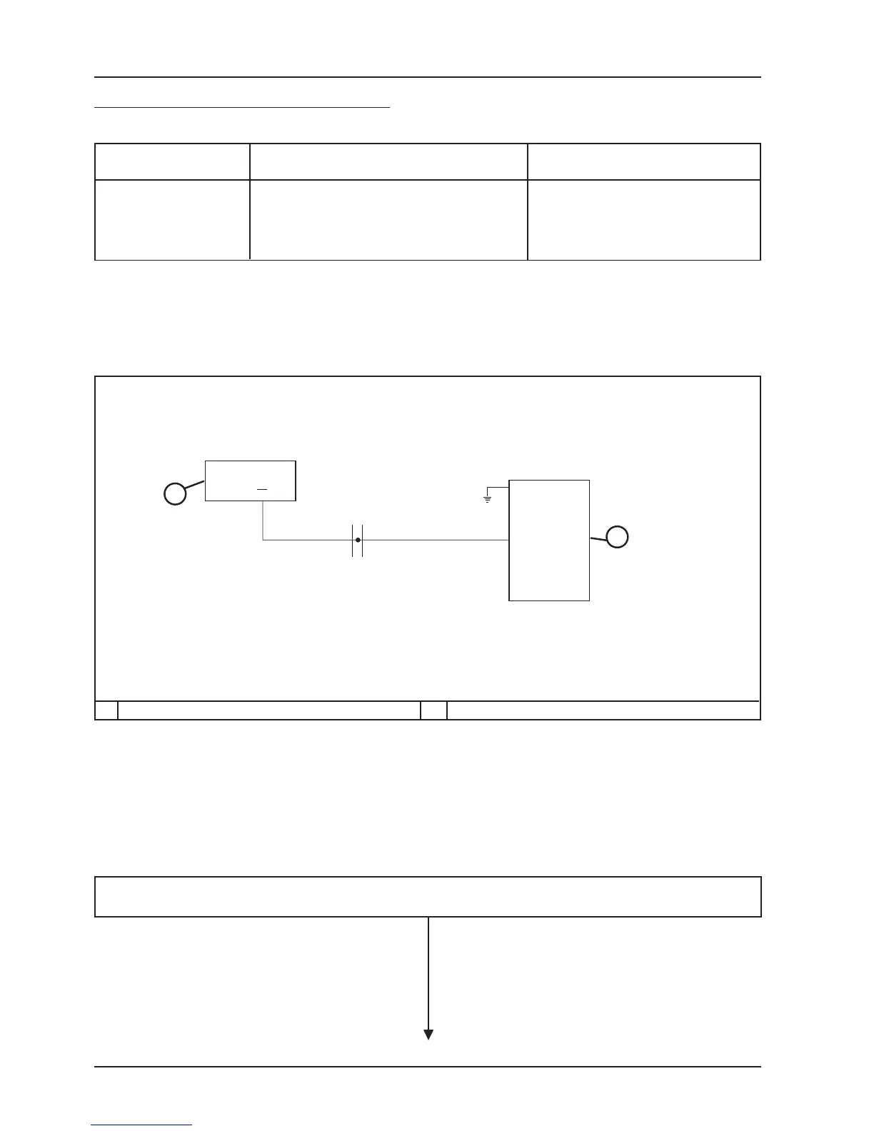
CIRCUIT DIAGRAM
The analog revolutions counter receives commands from the digital instrument panel which in turn receives signals
from the fuel injection control unit.
To control the revolutions counter and related circuit, proceed as follows:
REVOLUTIONS COUNTER CONTROL CIRCUIT
Terminals Conditions Standard
Ignition set to "ON"
Switch set to "RUN"
Side stand raised
Engine stopped
3 - 23 9 - 10 Volt
While pressing down both the clock and “S” buttons, set ignition to “ON”.
The digital instrument commands general check of the warning lights and instrument.
2
23
1
3
4
12
1 CONTROL UNIT 2 DIGITAL INSTRUMENT
VEHICLE
SYSTEM
FUEL INJECTION
SYSTEM
 Loading...