4.16
Cleanfire Fuel Injection
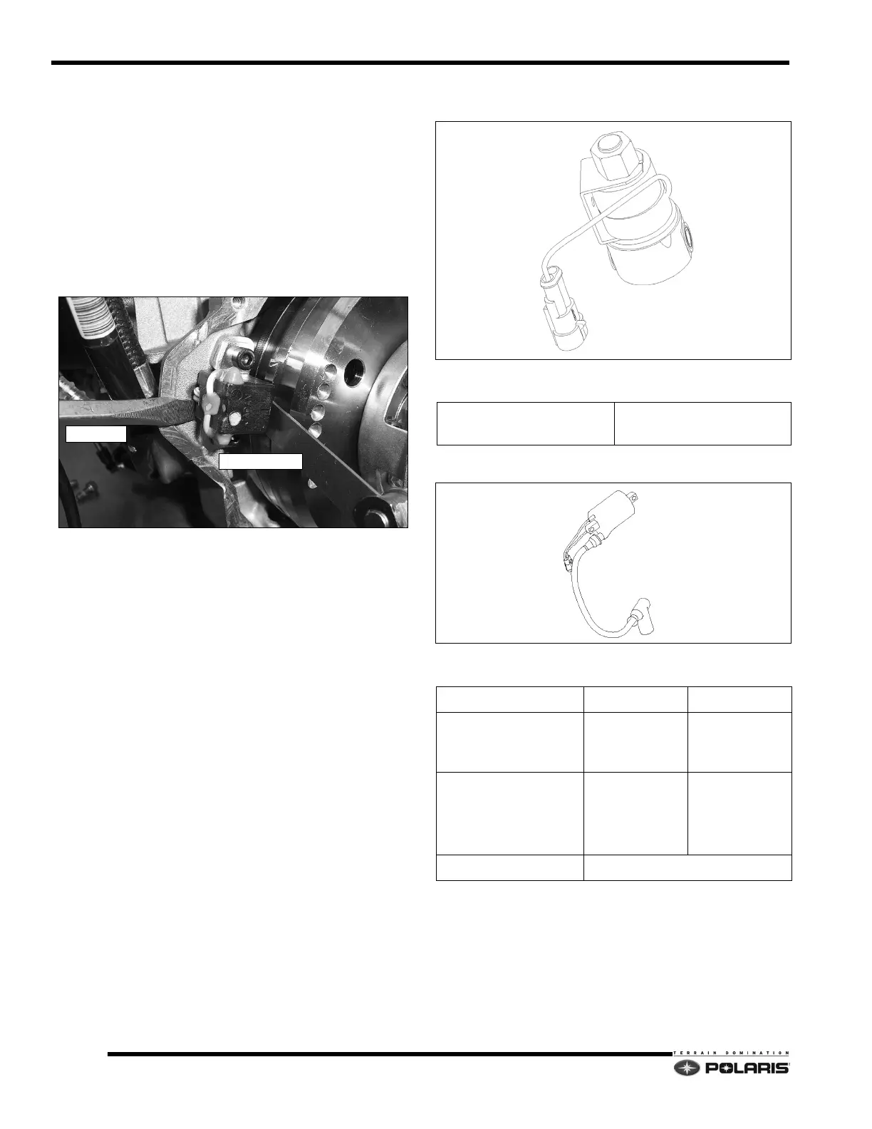
2. Insert the blade of a .030" feeler gauge between the
rib and sensor face. If there is no drag felt on the feeler
gauge, the CPS must be adjusted.
3. To adjust a CPS, use an 8 inch pry bar to carefully
de
flect the sensor.
4. Place the tip of the small pr
y bar between the back of
the sensor and crankcase. insert a .012" feeler gauge
between the sensor face and encoder rib.
IMPORTANT: Do not pry on the individual sensor
wir
es.
5. Gently pry the sensor towards the encoder rip until the
g
auge begins to bind between the components.
6. Re-measure the air gap. The gap should be between
.0
20-.030.
Exhaust Valve Solenoid
Ignition Coils
Specifications
Coil Resistance
(WHT/YEL to RED)
15 +/-
15% @ 68°F (20°C)
Specifications
DC-CFI 4 DC-CFI 2
Primary Coil
Resist
ance
(Black to White)
0.20 +/-
15%
@ 68°F (20°C)
0.45 +/- 15%
@ 68°F (20°C)
Secondary Coil
Resist
ance
(Without Plug Cap/
Black to
High Tension
Lead)
6.3k +/- 15%
@ 68°
F (20°C)
18k +/- 15%
@ 68°F (20°C)
Plug Cap Resistance 5k+
/- 15% @ 68°F (20°C)
 Loading...


