6.17
PVT System
6
DRIVE CLUTCH
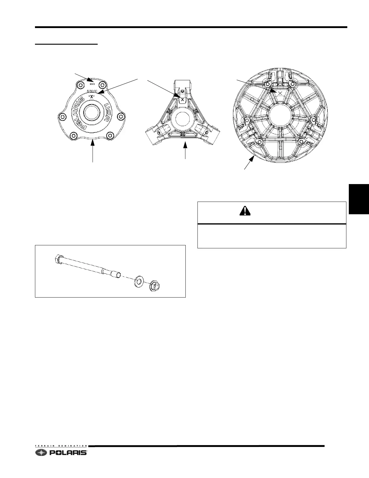
Identification
Every clutch will have the clutch part numbers etched on
to the cover (A). The “X" (B) marking is an index mark
where the clutch cover (C), clutch spider (D) and the
stationary sheave (E) should line up when the clutch is
assembled.
Drive Clutch Removal
NOTE: All clutch tools can be found at the beginning
of this chapter.
1. Remove the belt.
2. Place the clutch holding tool (PN 9314177-A) on the
dr
ive clutch.
3. Remove the drive clutch retaining bolt. N
ote the
placement and number of washers on retaining bolt.
4. Insert the correct clutch puller into the retaining bolt
ho
le.
5. Tighten the puller into the clutch. If the clutch does not
come off,
strike the clutch puller head with a hammer.
If the clutch does not “pop” off, continue to tighten the
clutch puller, and repeat this step.
Do not use an impact wrench to remove or install the
clutch bolt or clutch puller. Damage to the clutch and/or
crankshaft can occur.
 Loading...


