4.32
Cleanfire Fuel Injection
15. Using the PFA spanner wrench and nut socket
(PS48459), tighten the PFA to specification.
16. Fuel tank installation is the
reverse of removal. Always
test the PFA gasket seal before tank installation by
performing a pressure check.
Fuel Pump/Level Sender Test Specifications
The fuel level sender resistance can be checked using a
multimeter set to read resistance (OHMS).
Measure resistance at the fuel pump harness connector
be
tween pin 2 (WHITE/BLACK) and pin 4 (PINK/BLACK).
ARM UP/GAUGE READING FULL = <8
FLOAT HEIGHT FROM BOTTOM OF TANK = 345.3mm
+/-16.4
ARM MIDDLE/GAUGE READING 1/2 = 40.7+/- 1.5
FLOAT HEIGHT FROM BOTTOM OF TANK = 213.2mm
+/- 23.2
ARM DOWN/GAUGE READING EMPTY = 91.5 +/- 1.5
FLOAT HEIGHT FROM BOTTOM OF TANK =
89.6mm +/- 20.8
Fuel Tank Pressure Test
1. Connect a Mity Vac hand pump to the fuel tank vent
fitting.
2. Connect an eight-inch piece of 5/16
fuel hose and
two gear clamps across the fuel supply and return
fittings at the fuel pump flange.
3. Pressurize the tank to 5 PSI (34 Kpa).
NOTE: Fuel tank deformation will occur when the
t
ank is pressurized.
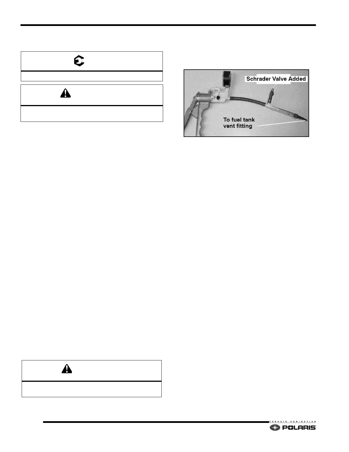
NOTE: Using a hand pump to pressurize the fuel
t
ank may take a very long time. The installation of an
in-line Schrader Valve (PN: 2872602) and the use of a
low pressure pump (bicycle tire pump) is
recommended.
4. Once the tank is pressurized, saturate the area
aro
und the PFA gasket with a mixture of water and
mild detergent.
5. If any bubbles form, re-check the PFA nut torque. If
bubble formation
continues, the PFA gasket will have
to be replaced, or tank replacement is required.
NOTE: There may be bubbles present from the initial
applica
tion of leak detector. Blow on the bubbles to
pop them. Watch for new bubble formation. New
bubble formation may be very small so look closely.
Apply additional water/detergent solution if required.
PFA Nut Torque: 28 ft-lbs (38 Nm)
Verify the PFA nut does not make contact with the fuel
tank after applying torque.
Do not over-pressurize the fuel tank past 6 PSI
(41 Kpa).
 Loading...


