8.31
Steering and Suspensions
8
Handlebar Centering
1. Raise the vehicle to remove the skis.
2. Verify the handlebars are straight. Measure from each
b
ar end to a common center point at the rear of the
vehicle.
3. Verify the steering drag link is not damaged, bent, or
lo
ose. If it is, the drag link must be either adjusted or
replaced. If the drag link is correct, adjust the steering
linkage tie rod ends until handlebar is centered. Note
that the toe setting will require adjustment.
4. Reinstall the spindle rod ends, bushings, and skis.
To
rque bolts to specification.
Camber
On a snowmobile, camber is the angle of the spindle
relative to vertical as viewed from the front. The camber
angle becomes increasingly more negative as the control
arms deflect upward.
• 0 = Neutral Camber. The spindle is perpendicular
t
o the ground.
• + = Positive Camber. The top of the spindle is
ca
nted outward from the chassis.
• - = Negative Camber. The top of the spindle is
ca
nted inward towards the chassis.
Camber Adjustment
1. Verify the handlebars are centered. Measure from
each end to a common center point at the rear of the
snowmobile if necessary.
2. Raise the front of the snowmobile off the ground.
Re
move the skis and ski bushings.
3. Verify the shocks are at full e
xtension and that no IFS
components are bent or damaged. Replace any
component that is damaged before making any
adjustments.
4. Insert the alignment bar, PN 5333508 or equivalent,
th
rough one spindle. Adjust the opposing spindle’s
upper control arm rod end to adjust the angle of the
spindle.
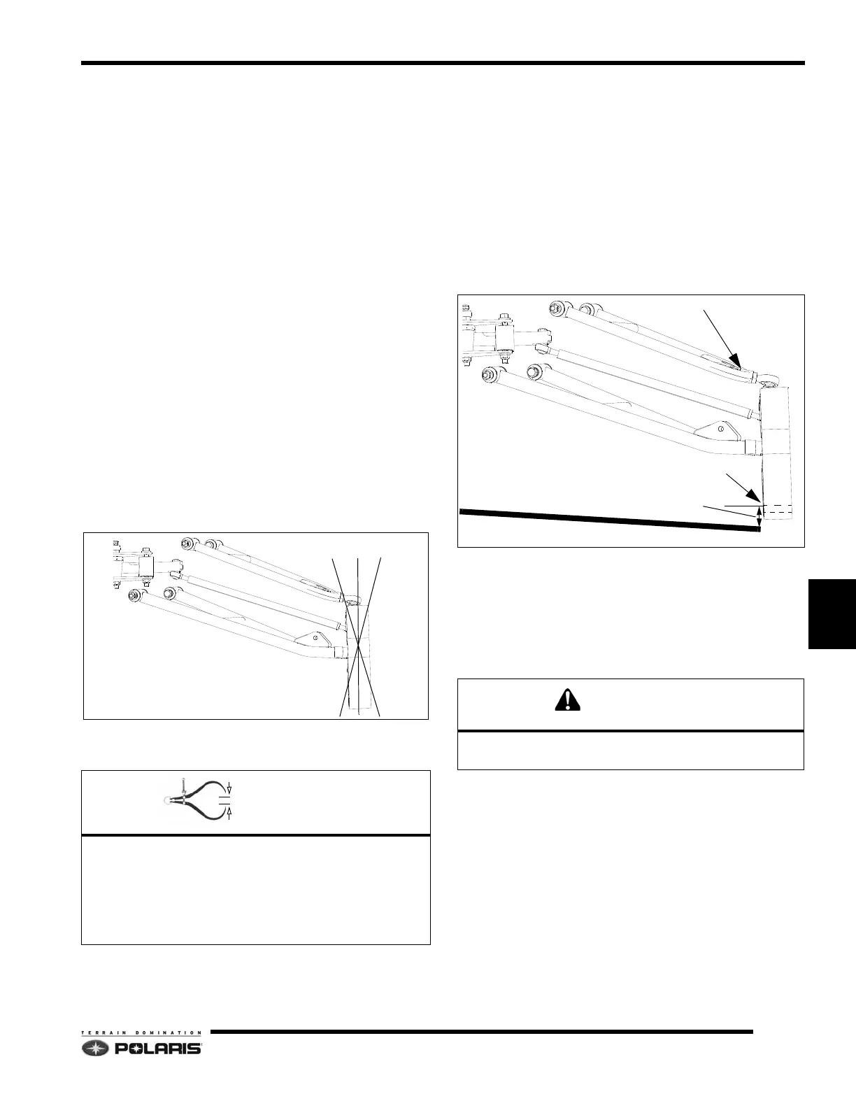
5. Check the measurement between the top-end of the
alig
nment bar and the top of the spindle’s bushing/ski
bolt hole (see illustration below).
6. Insert the alignment bar into the opposite spindle and
pe
rform the same steps. Monitor the specified camber
measurement as the control arm rod end nuts are
adjusted.
7. Continue making small rod end changes to both
co
ntrol arm rod end nuts until the camber setting
specification is achieved at both spindles.
8. Verify the upper rod ends are torqued to specification.
En
sure the rod ends remain parallel to the spindles
when torquing nuts.
9. Apply a liberal amount of Premium Grease to the ski
b
ushings, and then reinstall the bushings and skis.
Torque fasteners to specification.
Camber Setting
Top of alignment bar to top of ski bushing / bolt spindle
hole.
Pro-Ride = 1.68±.31/42±0.8
Pro-Ride RMK Adjustable = 1.95 0.31/4.3 0.8
Pro-Ride Wide Adjustable = 2.25 0.31/5.7 0.8
DO NOT EXCEED THE MAXIMUM SETUP WIDTH
SETTING WHEN ADJUSTING CAMBER.
ALIGNMENT BAR
BUSHING / BOLT HOLE
CAMBER SETTING DISTANCE
UPPER CONTROL ARM ROD END NUT
 Loading...


