5.10
Final Drive/Brake System
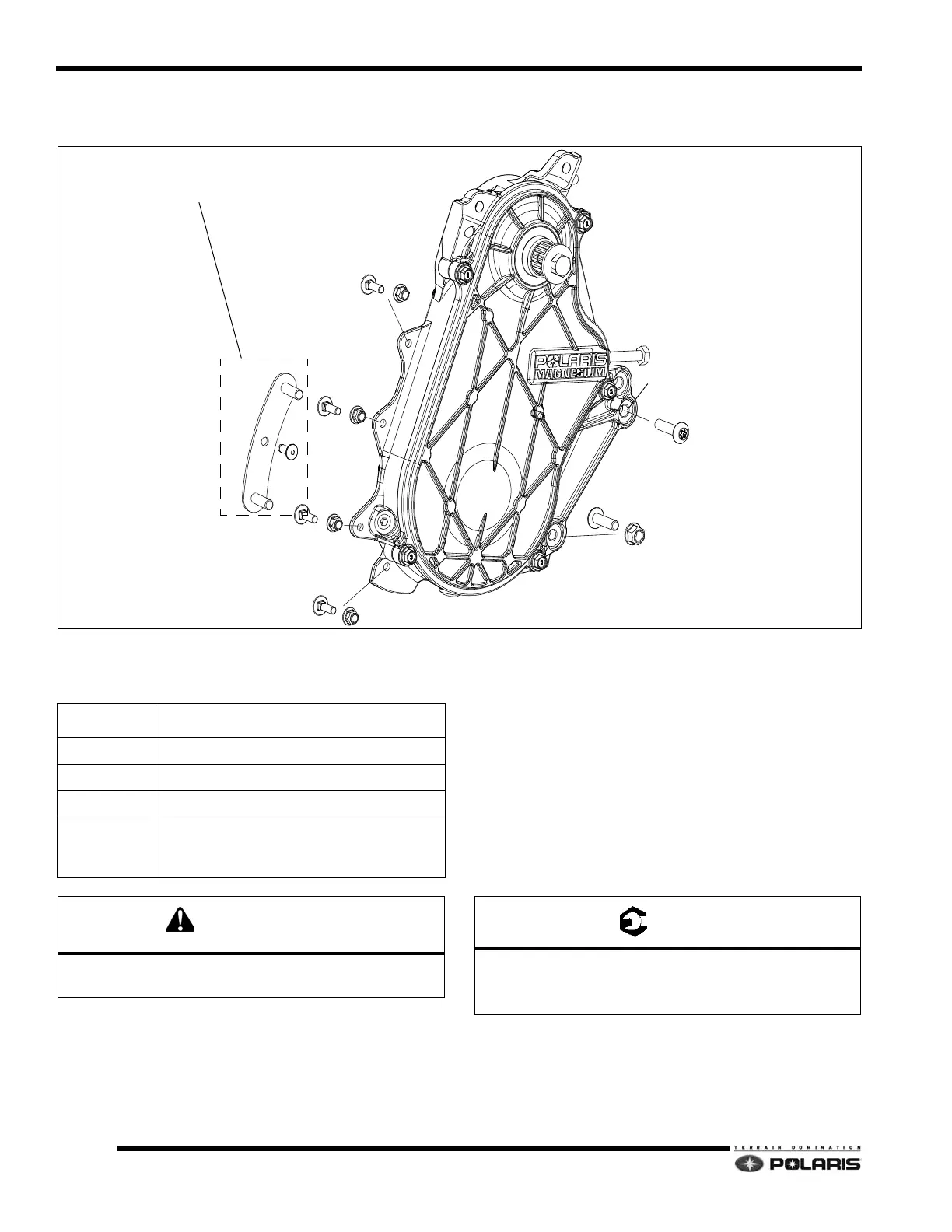
Mounting Assembly View
NOTE: 2012-2013 Pro-Ride models feature a bonded
chaincase.
Non-Bonded Chaincase Removal/
Installation
1. Follow the procedures for chaincase disassembly.
2. Follow the procedures for removing the track and
d
riveshaft.
3. Remove the fasteners securing the chaincase to the
t
unnel, front cooler/closeoff panel, and side support.
4. Inspect the seals for excessive wear or damage.
R
eplace as required.
5. Verify bearings roll smoothly. Rep
lace if they do not
or if excessive play is evident. Use an arbor press to
remove and install bearings.
6. To install the chaincase, loosely install all of the
f
asteners using new lock nuts where applicable.
7. Verify fastener (1) is installed in the lower chaincase
mounting hole
has shown in the illustration.
8. Torque fasteners to specifications.
9. Follow the procedures for reins
talling the driveshaft
and track.
10. Follow the procedures for chaincase assembly.
1
2
3
3
3
3
A
B
C
C
C
C
Align with bulkhead cooler.
4
Stud Plate-RMK Models Only
Tunnel Reinforcement Plate-Switchback Only
REFERENCE # DESCRIPTION
1 Screw-M8x1.25x35.8
2 Screw - M8x1.25x30.8
3 Carriage Bolts-M6x1.0x20
4
Stud Plate (RMK models only)
R
einforcement Plate (Switchback only-not
shown.)
Do not re-use lock Nuts. Always replace with new parts
after removal.
A: 26 ft-lbs (35 Nm) DO NOT OVER-TORQUE
B: 26 ft-lbs (35 Nm)
C: 14 ft-lbs (19 Nm)
 Loading...


