4.46
Cleanfire Fuel Injection
TPS Tests
Two tests can be performed to quickly determine if further testing is required.
TEST 1: TPS Idle Voltage
1. Connect Digital Wrench® to the vehicle. Confirm the throttle
lever free play is set to specification, and the throttle
cable is not pulling on the throttle plate cam.
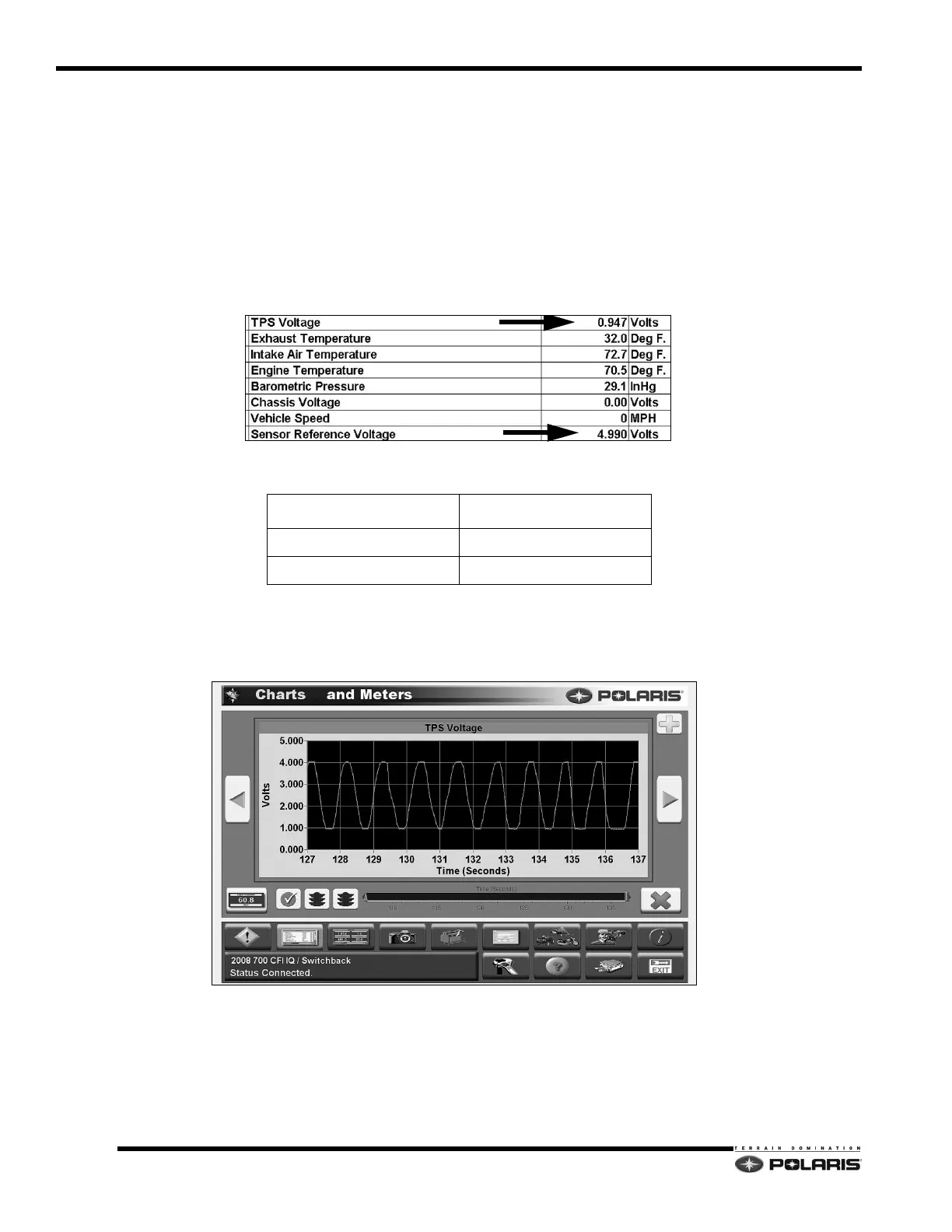
2. Click on the DATA GRID ICON to view the current
sensor readings.
3. Locate the TPS VOLTAGE reading and compare it to the specification for the v
ehicle. Verify SENSOR REFERENCE
VOLTAGE is 4.9-5.0 VDC.
TEST 2: TPS Signal Sweep
Utilize the sensor graph function to
view the TPS voltage return signal voltage as a line graph.
1. Slowly move the throttle lever
in and out. The return signal line should change without any erratic jumps or gaps.
2. If erratic jumps or gaps are encountered, inspect the wirin
g, and connector pins at the sensor and ECU connector.
3. If no wiring problems are found, inspect the TPS to v
erify it is securely mounted to the throttle body. If loose, it will
have to be readjusted.
4. Replace the TPS if steps 3 and 4 do not resolve the issue.
TPS Idle Base Setting Voltage
MODEL SPECIFICATION
600 DC-CFI Engine .94-.96 VDC
800 DC-CFI Engine .93-.95 VDC
 Loading...


