5.17
Final Drive/Brake System
5
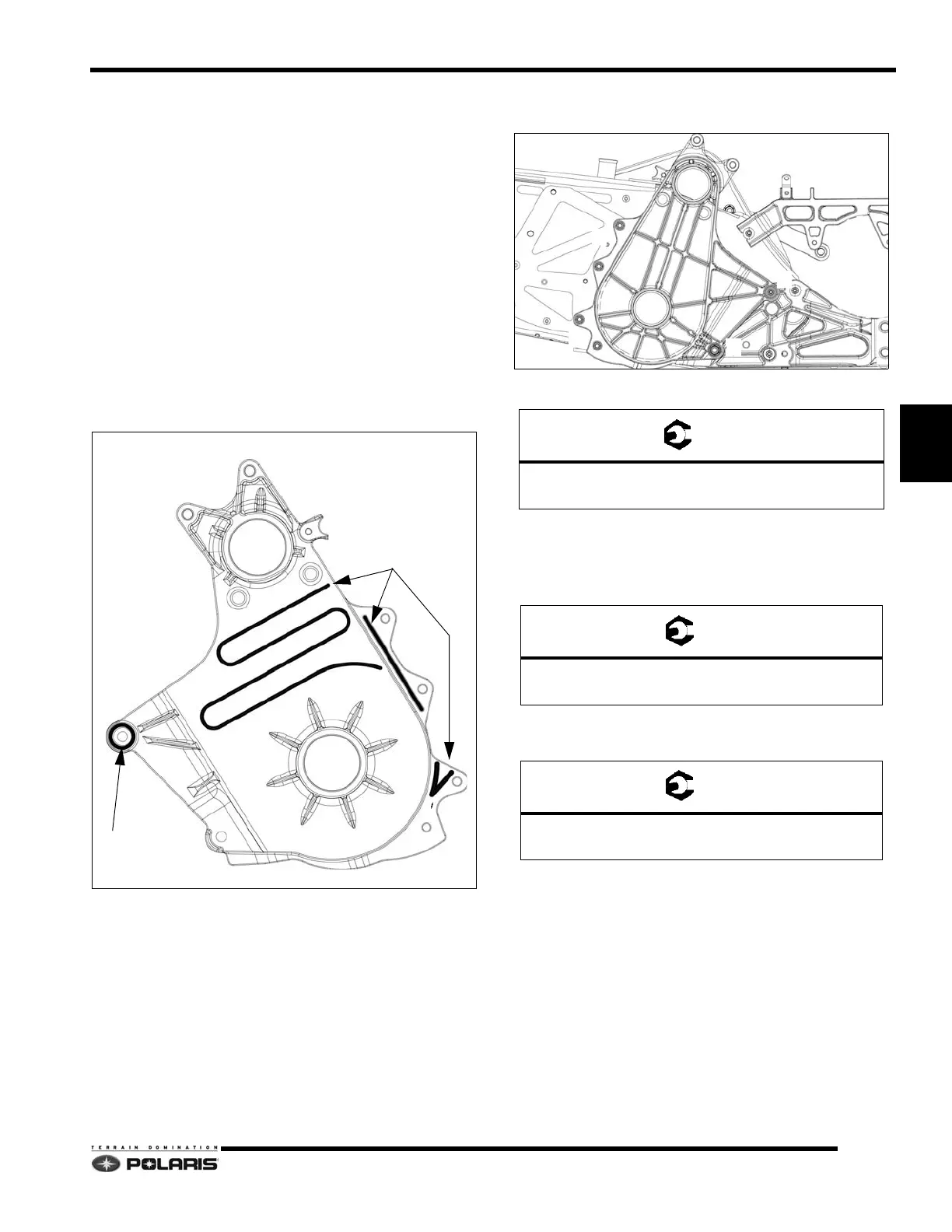
QuickDrive™ Backer Plate Installation
1. Begin backer plate installation by verifying all
fasteners are accounted for and staged for
installation.
2. Verify the backer plate and tunnel mating surfaces are
clea
n and free of dirt, and oil residue.
3. Reference Adhesive Applicator Kit and Adhesive
App
lication sections in Chapter 9. See “Bonded
Component Service” on page 9.25.
NOTE: The Bonded Component Service section in
Chap
ter 9 outlines the adhesive, applicator tools, and
the adhesive application procedure required to
properly install bonded components.
4. Apply adhesive to the backside of the backer plate as
sh
own.
5. After the adhesive has been applied to the backside
of the b
acker plate, quickly install all of the fasteners.
See “QuickDrive™ Backer Plate Assembly View” on
page 5.15.
6. Torque fasteners to specifications.
7. Follow the procedures for reinstalling the driveshaft
an
d track.
8. Install the brake disc. Install the vehicle speed sensor.
T
orque screw to specification.
9. Install the brake caliper assembly. Torque brake
caliper s
crews to specification.
10. Follow the procedure for installing the
drive belt and
sprockets.
A: 26 ft-lbs (35 Nm) DO NOT OVER-TORQUE
B: 9 ft-lbs (12 Nm)
Speed Sensor Screw
7 ft-lbs (10 Nm)
Brake Caliper Screws
18 ft-lbs (25 Nm)
 Loading...


