1.Checktheselectedlocationfortheunit.Aclear,
atareawithsuitableclearancebehindthepanel
isrequired.
2.Beforemodifyingthemountingsurface,refer
tothedimensionssuppliedinthisdocumentto
ensurethereisenoughspaceforthedisplayand
allcables.
3.Fixthesuppliedmountingtemplatetothe
selectedlocation,usingmaskingorself-adhesive
tape.
4.Usingasuitableholesaw(thesizeandposition
isindicatedonthetemplate),makeaholeineach
cornerofthecut-outarea.
5.Usingasuitablesaw,cutalongtheinsideedge
oftherearcasingcut-outlineindicatedonthe
template.
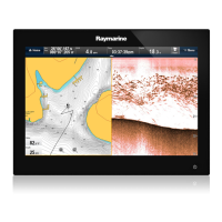
6.Followtherebatecut-outlineonthetemplateto
cutarebatearoundtheholewithadepthof8.5
mm(0.33in),toacceptthedisplay.
7.Ensurethattheunittsintotheremovedarea
andthenremoveanyroughedges.
8.Afxthesuppliedgasketontotherearofthe
displayandpressrmlyontotheange.
9.Connectthepower,dataandothercablestothe
unit.
10.Attachthesuppliedmountingbracketstothe
rearofthedisplayusingthesuppliedxings,as
showninthediagrambelow.Useonebracketfor
eachsideofthedisplay.
Note:Refertothe5.1Bracketmountinghole
locationssectionfordetailsofthelocationofthe
bracketmountingholesontherearofyourdisplay.
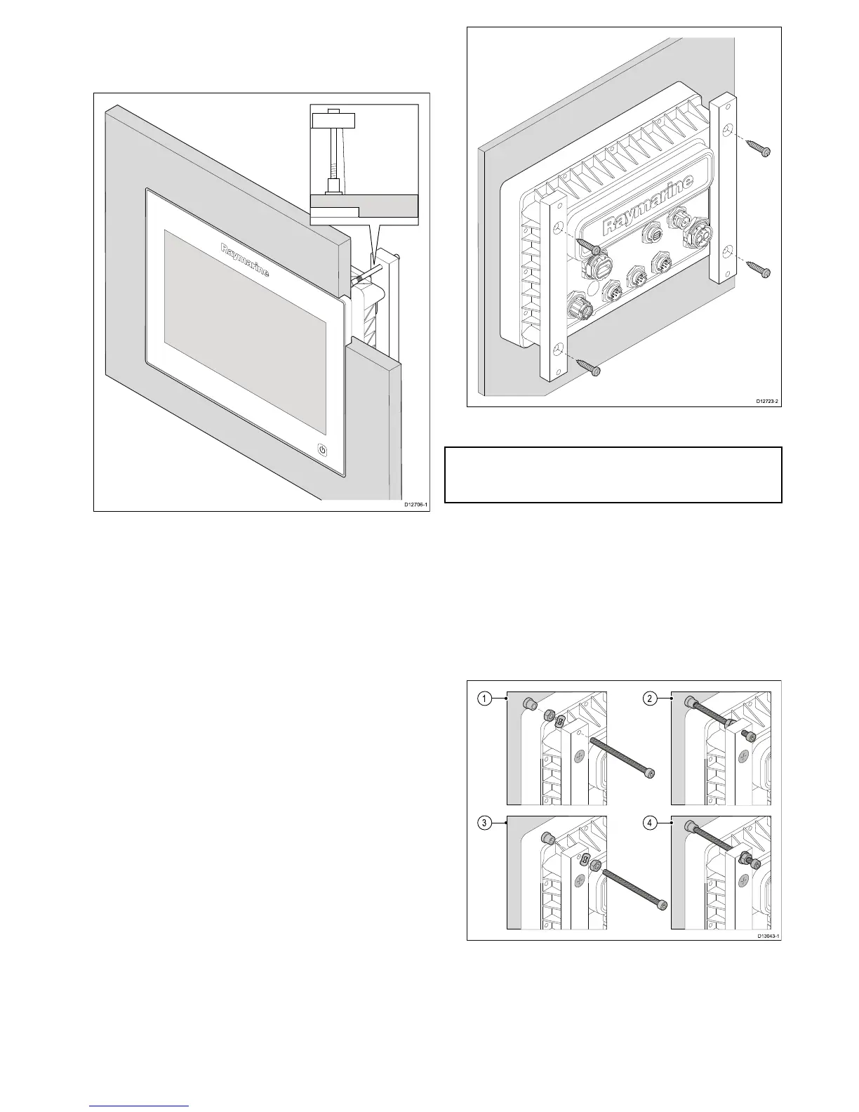
11.Securethedisplayusingtheprovidedmounting
xings(bolt,washer,locknutandfoot.In4
locations.
Dependingonthethicknessofthemounting
surfacethewasherandlocknutmaybelocated:
1.betweenthemountingbracketandmounting
feet(asshownin(1)and(2)below,or
2.afterthemountingbracketasshownin(3)
and(4)below.
 Loading...