PG-FP5 CHAPTER 4 PROGRAMMING GUI USAGE
R20UT0008EJ0400 Rev. 4.00 Page 102 of 240
Jul 15, 2010
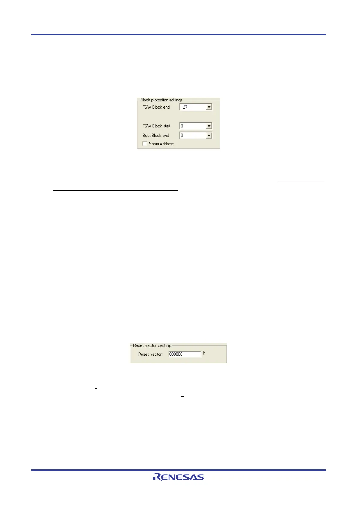
<6> [Block protection settings] area
In this area, block settings when the [Disable Boot block cluster reprogramming] check box is selected and block
settings for the flash shield window function can be performed.
Figure 4-73. [Block protection settings] Area
[Boot Block end] drop-down list
Select a block number from this list if the [Disable Boot block cluster reprogramming] check box is selected. This
list shows the block numbers where the flash memory in the target device is configured. Refer to the user’s
manual of each target device for the setting method.
[FSW Block start] and [FSW Block end] drop-down lists
Select the block subject to the flash shield window function, using these lists. Only the specified range can be
written through flash memory self programming. This setting does not affect programming using the programmer.
This function can prevent areas out of the specified range from being written to by mistake during flash self
programming. These lists show the block numbers where the flash memory in the target device is configured.
Refer to the user’s manual of each target device for the setting method.
[Show Address] check box
Specify the display format in the [Boot Block end], [FSW Block start] and [FSW Block end] drop-down lists. If this
check box is selected, the block address is displayed. If this check box is cleared, the block number is displayed.
<7> [Reset vector setting] area
The reset vector handling function can be set in this area.
Figure 4-74. [Reset vector setting] Area
[Reset vector] text box
If the [Set Security
] command is executed with an arbitrary address value input, the reset vector is changed to the
specified address. This setting is cleared if the [E
rase] command is executed with “Chip” selected in the
[Operation Mode] area.

 Loading...


