PG-FP5 CHAPTER 4 PROGRAMMING GUI USAGE
R20UT0008EJ0400 Rev. 4.00 Page 73 of 240
Jul 15, 2010
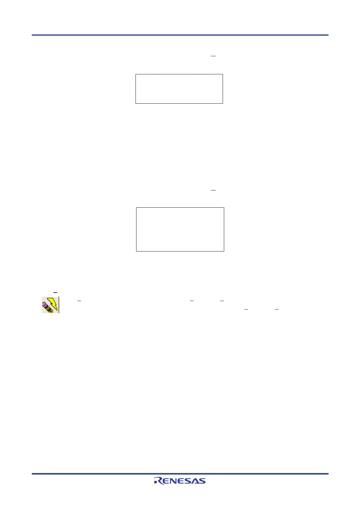
Figure 4-42. Action Log Window After [Checksum
] Command Execution
<When using 78K0, 78K0S (other than 78K0S/Kx1+ microcontrollers and
μ
PD78F9334), 78K0R, or V850>
Remark With the 16-bit arithmetic (subtraction) mode, the lower 4 digits of the result from which a value is
subtracted from 00h in 1-byte units are displayed.
<When using a 78K0S/Kx1+ microcontroller or
μ
PD78F9334>
Method: Division (original)
Range: Area set in the [Operation Mode] area on the [Standard] tab in the Device Setup dialog box
Figure 4-43. Action Log Window After [Checksum] Command Execution
<When using 78K0S/Kx1+ microcontroller or
μ
PD78F9334>
Remark For details on the arithmetic specifications, refer to Figure B-4 Division (Original) Calculation
Specifications.
(8) [Autoprocedure(E.P.)] command
The [A
utoprocedure(E.P.)] command executes the [Erase] and [Program] commands in succession. Exiting
from the flash memory programming mode is not possible between the [Erase] and [Program] commands.
The target area can be set in the [Operation Mode] area on the [Standard] tab in the Device Setup dialog box.
The progress status of this command is displayed in the action log window. When execution of this command is
completed, the programming GUI displays the result of command execution in the target device. Command
options after execution of this command depend on the settings of the [Blank check before Erase], [Verify after
Program], [Security after Program], and [Checksum after Program] check boxes in the [Command options] area on
the [Advanced] tab in the Device Setup dialog box. For details on these check boxes, refer to 4.3.3 (14) (c) <2>
[Command options] area.
>sum
0x623E
PASS
>
>sum
Device Checksum: 0x1842
FP5 Checksum: 0x1842
Checksum compare: PASS
Checksum operation finished.
>

 Loading...


