RL78/F13, F14 CHAPTER 16 SERIAL INTERFACE IICA
R01UH0368EJ0210 Rev.2.10 1100
Dec 10, 2015
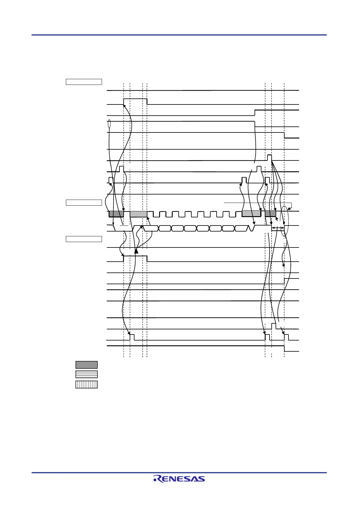
Figure 16-33. Example of Slave to Master Communication
(When 8-Clock and 9-Clock Wait Is Selected for Master, 9-Clock Wait Is Selected for Slave) (3/3)
(3) Data ~ data ~ stop condition
IICA0
STT0
(ST trigger)
SPT0
(SP trigger)
ACKD0
(ACK detection)
WTIM0
(8 or 9 clock wait)
ACKE0
(ACK control)
MSTS0
(communication status)
TRC0
(transmit/receive)
SCLA0 (bus)
(clock line)
WREL0
(wait cancellation)
INTIICA0
(interrupt)
SDAA0 (bus)
(data line)
IICA0
STD0
(ST detection)
SPD0
(SP detection)
ACKD0
(ACK detection)
WTIM0
(8 or 9 clock wait)
ACKE0
(ACK control)
MSTS0
(communication
status)
TRC0
(transmit/receive)
WREL0
(wait cancellation)
INTIICA0
(interrupt)
D
15
0
Master side
Bus line
Slave side
H
L
H
L
L
L
ACK
NACK
D
16
7 D
16
6 D
16
5 D
16
4 D
16
3 D
16
2 D
16
1 D
16
0
Stop condition
Note 1
Note 1
Note 3
Note 2
Notes 1, 4
Note 4
<14>
<9>
<8> <11>
<10>
<12>
<13> <16>
<19>
<15>
<17>
<18>
: Wait state by master device
: Wait state by slave device
: Wait state by master and slave devices
Notes 1. To cancel a wait state, write “FFH” to IICA0 or set the WREL0 bit.
2. Make sure that the time between the rise of the SCLA0 pin signal and the generation of the stop condition
after a stop condition has been issued is at least 4.0
s when specifying standard mode and at least 0.6
s when specifying fast mode.
3. Write data to IICA0, not setting the WREL0 bit, in order to cancel a wait state during transmission by a
slave device.
4. If a wait state during transmission by a slave device is canceled by setting the WREL0 bit, the TRC0 bit
will be cleared.
 Loading...


