RL78/F13, F14 CHAPTER 12 A/D CONVERTER
R01UH0368EJ0210 Rev.2.10 754
Dec 10, 2015
12.8 SNOOZE Mode Function
In the SNOOZE mode, A/D conversion is triggered by inputting a hardware trigger in the STOP mode. Normally, A/D
conversion is stopped while in the STOP mode, but, by using the SNOOZE mode, A/D conversion can be performed without
operating the CPU by inputting a hardware trigger. This is effective for reducing the operation current.
If the A/D conversion result range is specified using the ADUL and ADLL registers, A/D conversion results can be judged
at a certain interval of time in SNOOZE mode. Using this function enables power supply voltage monitoring and input key
judgment based on A/D inputs.
In the SNOOZE mode, only the following two conversion modes can be used:
Hardware trigger wait mode (select mode, one-shot conversion mode)
Hardware trigger wait mode (scan mode, one-shot conversion mode)
Caution The SNOOZE mode can only be specified when the high-speed on-chip oscillator clock is selected for
f
CLK.
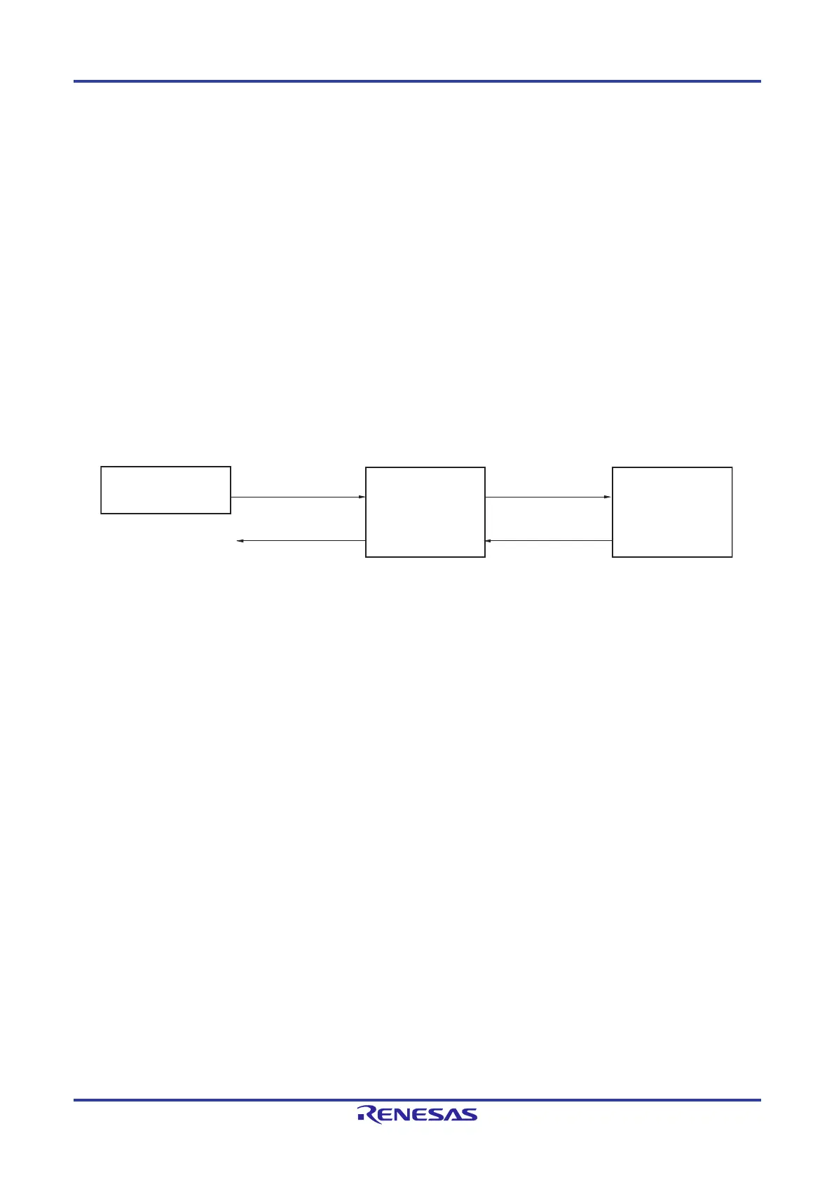
Figure 12-39. Block Diagram When Using SNOOZE Mode Function
When using the SNOOZE mode function, the initial setting of each register is specified before switching to the STOP
mode. (For details about these settings, see 12.7.3 Setting up hardware trigger wait mode
Note 2
.) At this time, bit 2
(AWC) of A/D converter mode register 2 (ADM2) is set to 1. After the initial settings are specified, bit 0 (ADCE) of A/D
converter mode register 0 (ADM0) is set to 1.
If a hardware trigger is input after switching to the STOP mode, the high-speed on-chip oscillator clock is supplied to the
A/D converter. After supplying this clock, the system automatically counts up to the stabilization wait time, and then A/D
conversion starts.
The SNOOZE mode operation after A/D conversion ends differs depending on whether an interrupt signal is generated
Note
1
.
Notes 1. Depending on the setting of the A/D conversion result comparison function (ADRCK bit, ADUL/ADLL register),
there is a possibility of no interrupt signal being generated.
2. Be sure to set the ADM1 register to E1H, E2H, or E3H.
Remark The hardware trigger is event selected by ELC, INTRTC, or INTTM01.
Specify the hardware trigger by using the A/D converter mode register 1 (ADM1).
Real-time clock (RTC),
event link controller (ELC)
Hardware trigger
input
Clock request signal
(internal signal)
High-speed on-chip
oscillator clock
A/D converter
Clock generator
A/D conversion end
interrupt request
signal
Note 1
(INTAD)
 Loading...


