RL78/F13, F14 CHAPTER 5 CLOCK GENERATOR
R01UH0368EJ0210 Rev.2.10 362
Dec 10, 2015
CHAPTER 5 CLOCK GENERATOR
Use the clock generator within a range that satisfies the values stipulated in CHAPTER 34 to CHAPTER 36
ELECTRICAL SPECIFICATIONS.
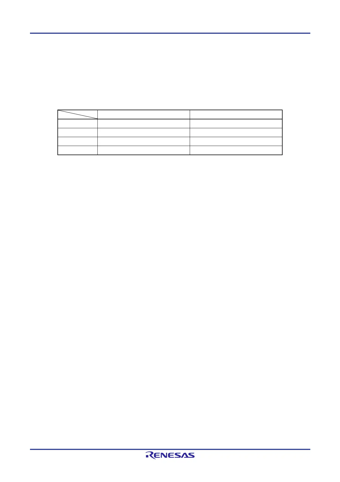
The presence or absence of connecting resonator pin for subsystem clock and external clock input pin for subsystem
clock depends on the product.
20-, 30-, and 32-pin products 48-, 64-, 80-, and 100-pin products
X1, X2 pins
EXCLK pin
XT1, XT2 pins
EXCLKS pin
Cautions 1. The 20-, 30-, and 32-pin products don’t have the subsystem clock.
2. Do not use the XT1 and XT2 pin functions in grade-Y products.
5.1 Functions of Clock Generator
The clock generator generates the clock to be supplied to the CPU and peripheral hardware.
The following three kinds of system clocks and clock oscillators are selectable.
(1) Main system clock
<1> X1 oscillator
This circuit oscillates a clock of f
X = 1 to 20 MHz by connecting a resonator to X1 and X2.
Oscillation can be stopped by executing the STOP instruction or setting of the MSTOP bit (bit 7 of the clock
operation status control register (CSC)).
<2> High-speed on-chip oscillator (High-speed OCO)
The frequency at which to oscillate can be selected from among f
IH = 64, 48, 32, 24, 16, 12, 8, 4, or 1 MHz
(TYP.) by using the user option byte (000C2H/020C2H). When 64 MHz or 48 MHz is selected as f
IH, fCLK is set
to 32 MHz or 24 MHz, respectively, after a reset release. The CPU always starts operating with this high-speed
on-chip oscillator clock
Note
. Oscillation can be stopped by executing the STOP instruction or setting of the
HIOSTOP bit (bit 0 of the CSC register).
The frequency set by using the user option byte can be changed by the high-speed on-chip oscillator frequency
select register (HOCODIV). For the frequency, see Figure 5-15 Format of High-speed on-chip oscillator
frequency select register (HOCODIV).
An external main system clock (f
EX = 1 to 20 MHz) can also be supplied from the EXCLK/X2/P122 pin. An external
main system clock input can be disabled by executing the STOP instruction or setting of the MSTOP bit.
As the high-speed system clock, an X1 clock or external main system clock can be selected by setting of the OSCSEL
bit (bit 6 of the clock operation mode control register (CMC)) and the EXCLK bit (bit 7 of the clock operation mode
control register (CMC)).
As the main system clock, a high-speed system clock (X1 clock or external main system clock) or high-speed on-
chip oscillator clock can be selected by setting of the MCM0 bit (bit 4 of the system clock control register (CKC)).
Note When selecting 64 MHz or 48 MHz, the selected clock (f
IH) is supplied to timer RD.
When supplying 64 MHz or 48 MHz to timer RD, set f
CLK to fIH.
 Loading...


