RL78/F13, F14 CHAPTER 18 CAN INTERFACE (RS-CAN LITE)
R01UH0368EJ0210 Rev.2.10 1404
Dec 10, 2015
18.10.1 Clock Setting
Set the CAN clock (f
CAN) as a clock source of the CAN module. Select the clock obtained by frequency-dividing fCLK by
2 (f
CLK/2) or the X1 clock (fx) with the DCS bit in the GCFGL register.
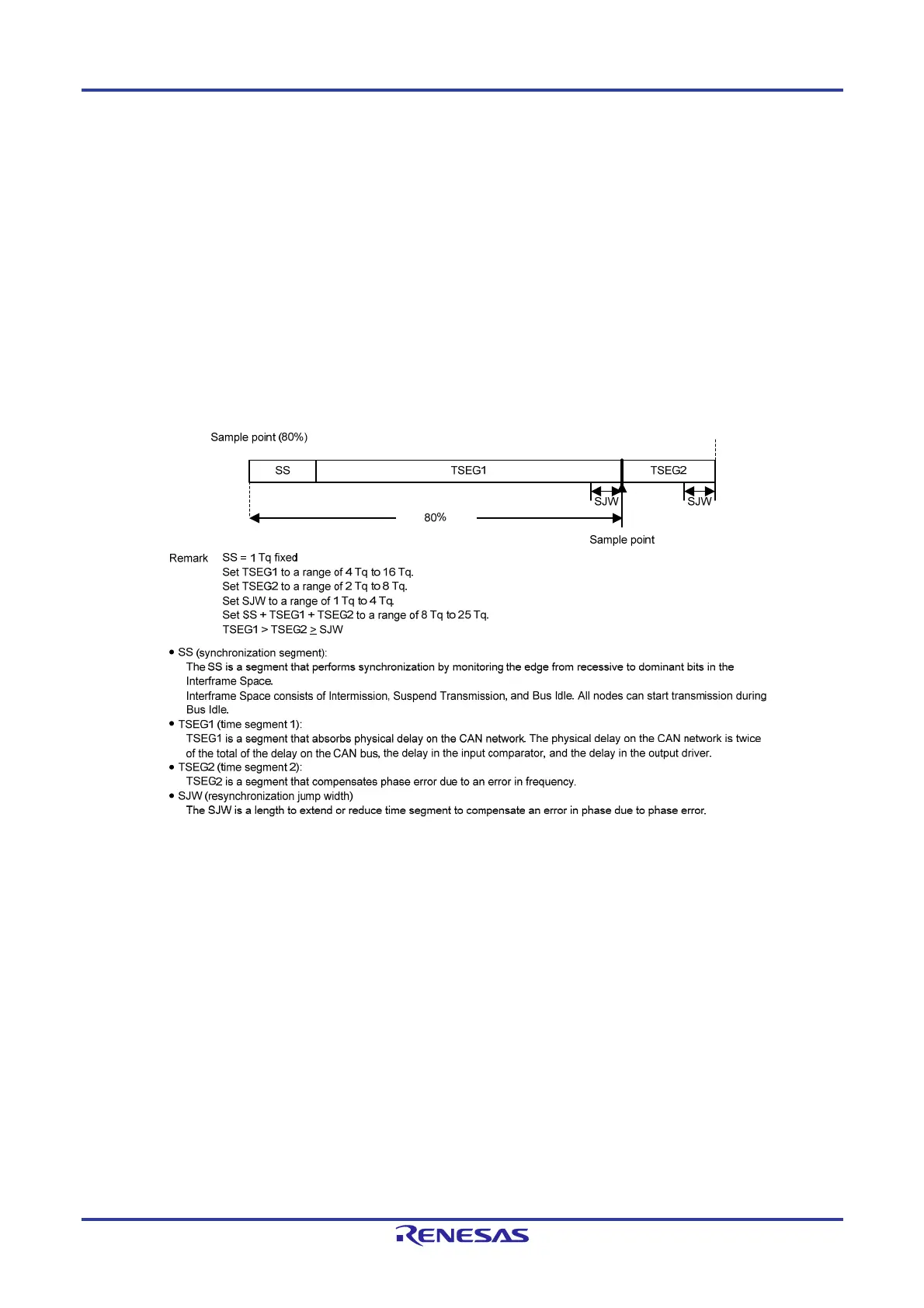
18.10.2 Bit Timing Setting
In the CAN protocol, one bit of a communication frame consists of three segments, SS, TSEG1, and TSEG2. Two of
the segments, TSEG1 and TSEG2, can be set by the CiCFGH register for each channel. Sample point timing can be
determined by setting two segments. This timing can be adjusted in units of 1 Time Quantum (referred to as Tq
hereinafter). 1 Tq equals to one CANi Tq clock cycle. The CANi Tq clock is obtained by selecting the clock source with the
DCS bit in the GCFGL register and selecting the clock division ratio with the BRP[9:0] bits in the CiCFGL register.
Figure 18-17 shows the bit timing chart. Table 18-13 shows an example of bit timing setting.
Figure 18-17. Bit Timing Chart
 Loading...


