RL78/F13, F14 CHAPTER 4 PORT FUNCTIONS
R01UH0368EJ0210 Rev.2.10 280
Dec 10, 2015
4.2.9 Port 9
Port 9 is an I/O port with an output latch. Port 9 can be set to the input mode or output mode in 1-bit units using port
mode register 9 (PM9).
This port can also be used for A/D converter analog input.
To use P90/ANI10 to P97/ANI17 as digital input pins, set them in the digital I/O mode by using the A/D port
configuration register (ADPC) and in the input mode by using the PM9 register. Use these pins starting from the upper bit.
To use P90/ANI10 to P97/ANI17 as digital output pins, set them in the digital I/O mode by using the A/D port
configuration register (ADPC) and in the output mode by using the PM9 register. Use these pins starting from the upper
bit.
To use P90/ANI10 to P97/ANI17 as analog input pins, set them in the analog input mode by using the A/D port
configuration register (ADPC) and in the input mode by using the PM9 register. Use these pins starting from the lower bit.
Reset signal generation sets this port to analog input mode.
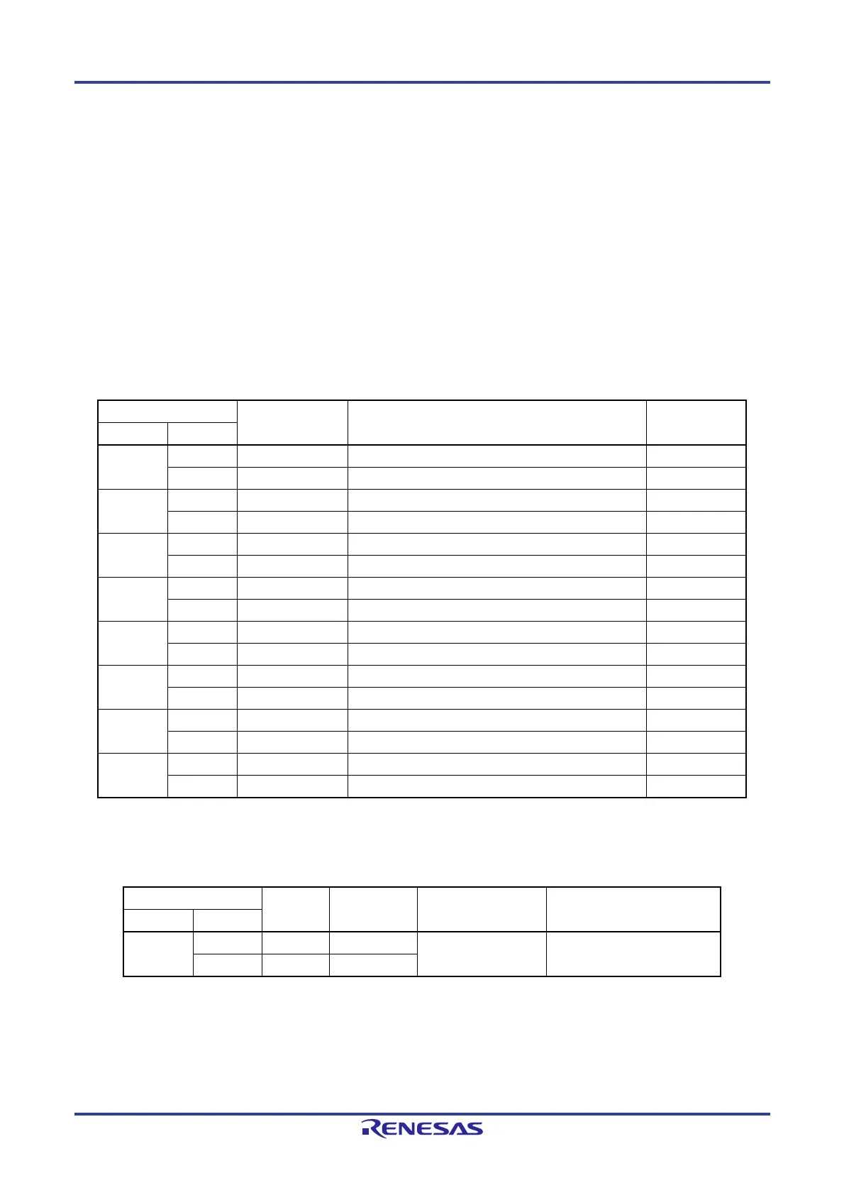
Table 4-16. Settings of Registers When Using Port 9
Pin Name PM9x Alternate Function Setting Remark
Name I/O
P90 Input 1
Output 0
P91 Input 1
Output 0
P92 Input 1
Output 0
P93 Input 1
Output 0
P94 Input 1
Output 0
P95 Input 1
Output 0
P96 Input 1
Output 0
P97 Input 1
Output 0
Remark : Don't care
PM9x: Port mode register 9
Table 4-17. Settings of Registers When Using Port 9
Pin Name PM9x ADPC
Alternate Function
Setting
Remark
Name I/O
P9n Input 1 0C to n+0CH
To use P9n as a port, use these
pins from the upper bit.
Output 0 0C to n+0CH
Remarks 1. PM9x: Port mode register 9
ADPC: A/D port configuration register
2. n = 0 to 7
 Loading...


