RL78/F13, F14 CHAPTER 4 PORT FUNCTIONS
R01UH0368EJ0210 Rev.2.10 283
Dec 10, 2015
4.2.10 Port 10
Port 10 is an I/O port with an output latch. Port 10 can be set to the input mode or output mode in 1-bit units using port
mode register 10 (PM10).
When the P106 and P107 pins are used as an input port, use of an on-chip pull-up resistor can be specified in 1-bit
units by pull-up resistor option register 10 (PU10). For the P107 pin input, the threshold of the input buffer can be specified
in 1-bit units using the port input threshold control register 10 (PITHL10).
This port can also be used for A/D converter analog input and LIN serial data I/O.
To use P100/ANI18 to P105/ANI23 as digital input pins, set them in the digital I/O mode by using the A/D port
configuration register (ADPC) and in the input mode by using the PM10 register. Use these pins starting from the upper
bit.
Reset signal generation sets this port to input mode.
To use P100/ANI18 to P105/ANI23 as digital output pins, set them in the digital I/O mode by using the A/D port
configuration register (ADPC) and in the output mode by using the PM10 register. Use these pins starting from the upper
bit.
To use P100/ANI18 to P105/ANI23 as analog input pins, set them in the analog input mode by using the A/D port
configuration register (ADPC) and in the input mode by using the PM10 register. Use these pins starting from the lower bit.
Reset signal generation sets this port to analog input mode.
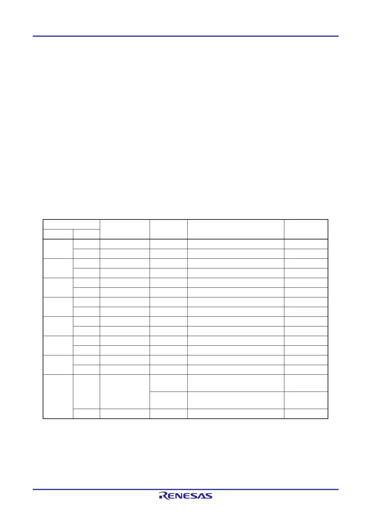
Table 4-19. Settings of Registers When Using Port 10
Pin Name PM10x PITHL10x Alternate Function Setting
Note 2
Remark
Name I/O
P100
Note 3
Input 1 —
Output 0 —
P101
Note 3
Input 1 —
Output 0 —
P102
Note 3
Input 1 —
Output 0 —
P103
Note 3
Input 1 —
Output 0 —
P104
Note 3
Input 1 —
Output 0 —
P105
Note 3
Input 1 —
Output 0 —
P106 Input 1 —
Output 0 — (LTXD1 output = 1)
Note 1
P107 Input 1 0
CMOS input
(Schmitt1 input)
1
CMOS input
(Schmitt3 input)
Output 0
Notes 1. When a pin sharing the serial data output function of the LIN is to be used as a general-purpose port pin,
operation of the corresponding LIN must be stopped.
2. Functions in parentheses can be assigned via settings in the peripheral I/O redirection register 4 (PIOR4).
3. These are the settings of registers in the case where setting of the A/D port configuration register (ADPC)
is to select “D” (digital I/O) for the target pin. See Table 4-20 when using this pin as an analog input.
Remark : Don't care
PM10x: Port mode register 10
PITHL10x: Port input threshold control register 10
 Loading...


