RL78/F13, F14 CHAPTER 6 TIMER ARRAY UNIT
R01UH0368EJ0210 Rev.2.10 479
Dec 10, 2015
6.6 Channel Output (TOmn pin) Control
6.6.1 TOmn pin output circuit configuration
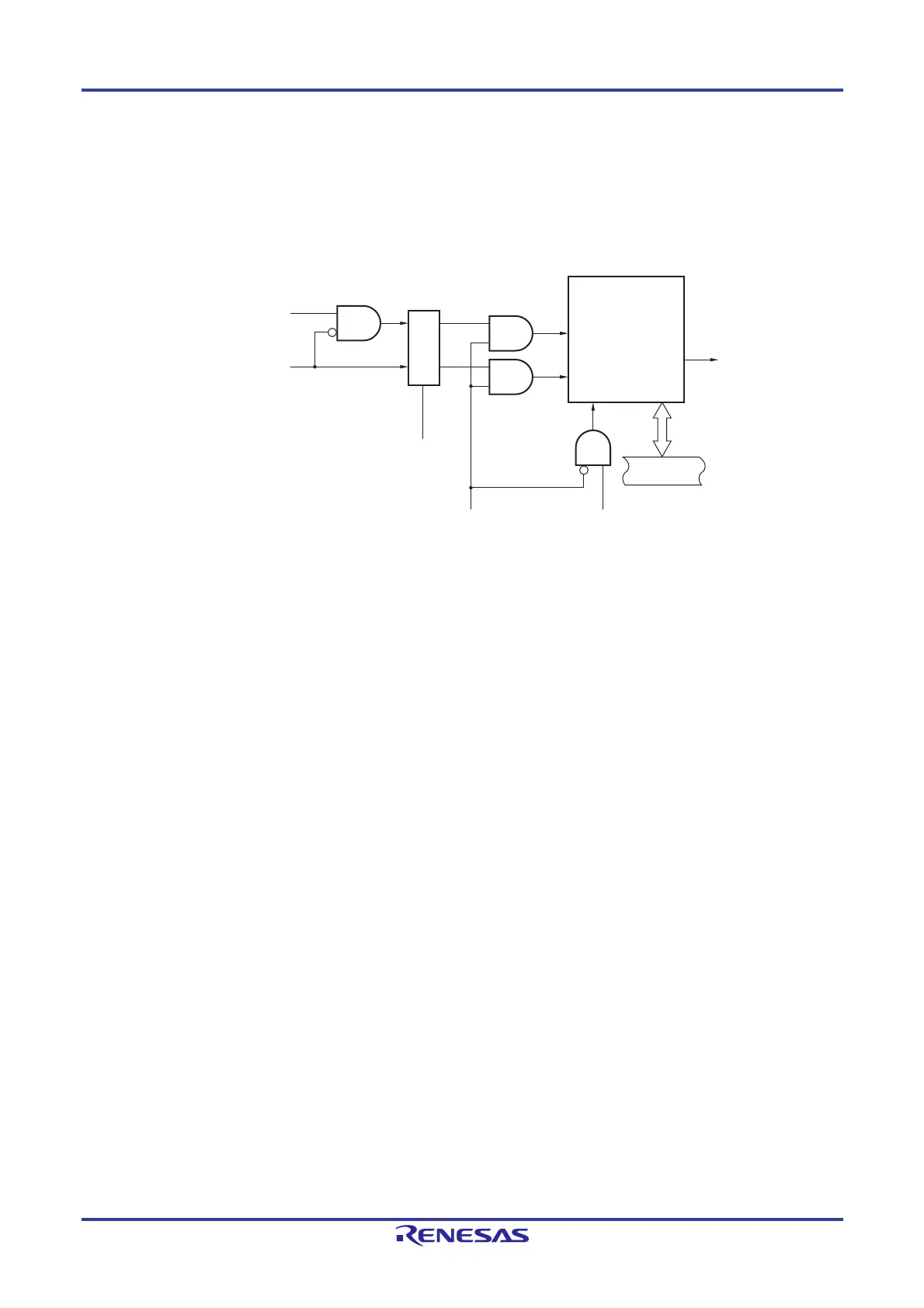
Figure 6-34. Output Circuit Configuration
The following describes the TOmn pin output circuit.
<1> When TOMmn = 0 (master channel output mode), the set value of timer output level register m (TOLm) is
ignored and only INTTM0p (slave channel timer interrupt) is transmitted to timer output register m (TOm).
<2> When TOMmn = 1 (slave channel output mode), both INTTMmn (master channel timer interrupt) and INTTM0p
(slave channel timer interrupt) are transmitted to the TOm register.
At this time, the TOLm register becomes valid and the signals are controlled as follows:
When TOLmn = 0: Forward operation (INTTMmn set, INTTM0p reset)
When TOLmn = 1: Reverse operation (INTTMmn reset, INTTM0p set)
When INTTMmn and INTTM0p are simultaneously generated, (0% output of PWM), INTTM0p (reset signal)
takes priority, and INTTMmn (set signal) is masked.
<3> While timer output is enabled (TOEmn = 1), INTTMmn (master channel timer interrupt) and INTTM0p (slave
channel timer interrupt) are transmitted to the TOm register. Writing to the TOm register (TOmn write signal)
becomes invalid.
When TOEmn = 1, the TOmn pin output never changes with signals other than interrupt signals.
To initialize the TOmn pin output level, it is necessary to set timer operation is stopped (TOEmn = 0) and to
write a value to the TOm register.
<4> While timer output is disabled (TOEmn = 0), writing to the TOmn bit to the target channel (TOmn write signal)
becomes valid. When timer output is disabled (TOEmn = 0), neither INTTMmn (master channel timer interrupt)
nor INTTM0p (slave channel timer interrupt) is transmitted to the TOm register.
<5> The TOm register can always be read, and the TOmn pin output level can be checked.
Remarks 1. m: Unit number (m = 0, 1)
n: Channel number
n = 0 to 7 (n = 0, 2, 4, 6 for master channel)
p: Slave channel number
n < p ≤ 7
2. Unit 1 is not provided in the Group A products.
Channels 7 to 4 of unit 1 are not provided in the Group B, C, and D products.
Interrupt signal of the master channel
(INTTMmn)
TOLmn
TOMmn
TOEmn
<1>
<2>
<3>
<4>
<5>
TOmn write signal
TOmn pin
TOmn register
Set
Reset/toggle
Internal bus
Interrupt signal of the slave channel
(INTTMmp)
Controller
 Loading...


