RL78/F13, F14 CHAPTER 6 TIMER ARRAY UNIT
R01UH0368EJ0210 Rev.2.10 478
Dec 10, 2015
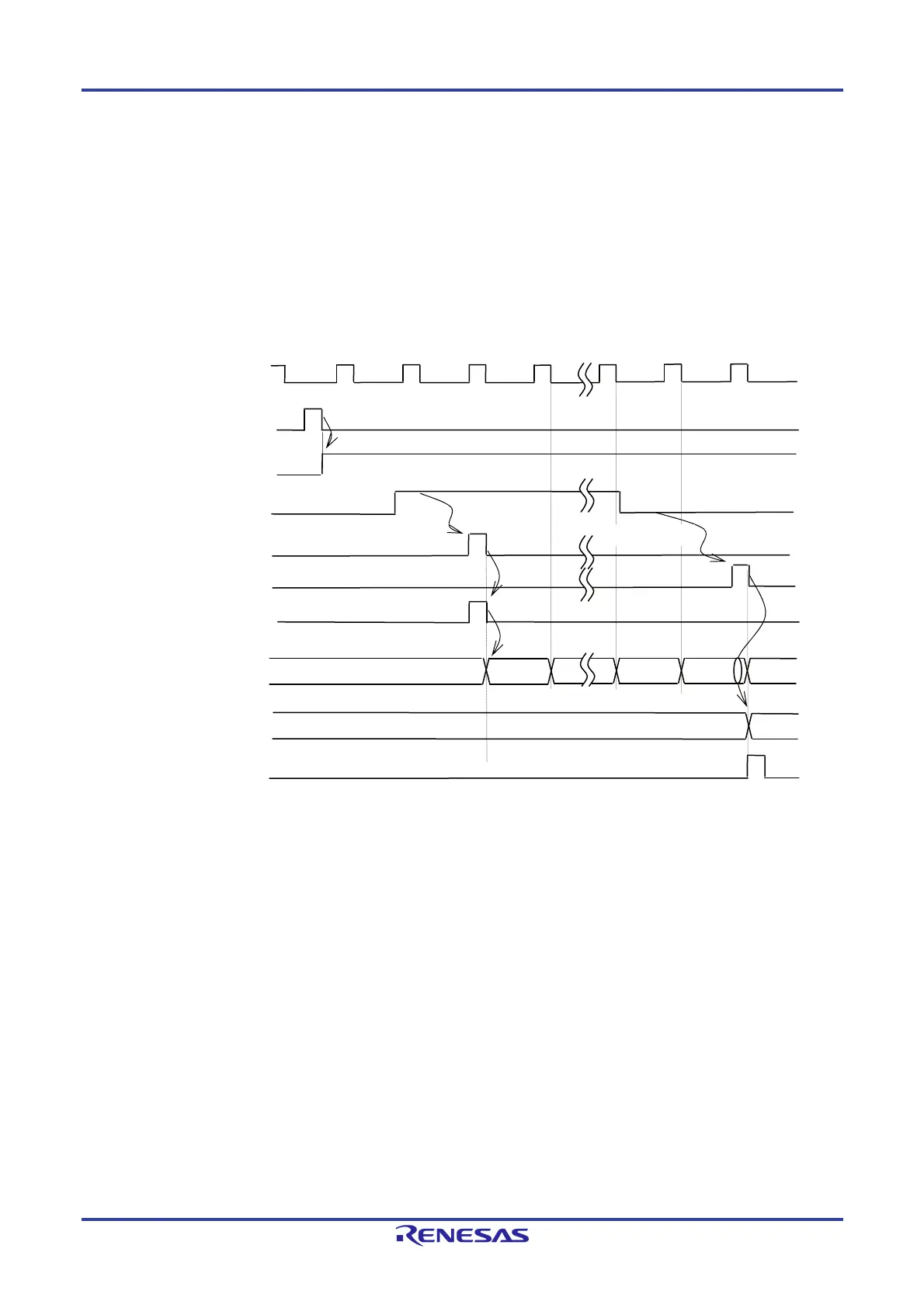
(5) Start timing in capture & one-count mode (when high-level width is measured)
<1> Operation is enabled (TEmn = 1) by writing 1 to the TSmn bit of timer channel start register m (TSm).
<2> Timer count register mn (TCRmn) holds the initial value until start trigger generation.
<3> Rising edge of the TImn input is detected.
<4> On start trigger detection, the value of 0000H is loaded to the TCRmn register and count starts.
<5> On detection of the falling edge of the TImn input, the value of the TCRmn register is captured to timer data
register mn (TDRmn) and INTTMmn is generated.
Figure 6-33. Start Timing (In Capture & One-count Mode)
Remark The timing is shown in Figure 6-33 indicates while the noise filter is not used. By making the noise filter
on-state, the edge detection becomes 2 f
MCK cycles (it sums up to 3 to 4 cycles) later than the normal cycle
of TImn input. The error per one period occurs because of the asynchronous relationship between the
period of the TImn input and that of the count clock (f
MCK).
fMC
(fTCLK)
TSmn(Write)
TEmn
TImn input
<1>
<2>
Rising edge
Edge detection
<4>
TCRmn
Initial value
m-1
m
TDRmn
Start trigger
detection signal
<3>
Falling edge
0000
m
Edge detection
0000
0000
INTTMmn
<5>
 Loading...


