RL78/F13, F14 CHAPTER 11 WATCHDOG TIMER
R01UH0368EJ0210 Rev.2.10 694
Dec 10, 2015
11.2 Configuration of Watchdog Timer
The watchdog timer includes the following hardware.
Table 11-1. Configuration of Watchdog Timer
Item Configuration
Counter Internal counter (17 bits)
Control register Watchdog timer enable register (WDTE)
How the internal counter (17 bits) operation is controlled, overflow time, window open period, and interval interrupt are
set by the option byte.
Caution Set the same value as 000C0H to 020C0H when the boot swap operation is used because 000C0H is
replaced by 020C0H.
Table 11-2. Setting of Option Bytes and Watchdog Timer
Setting of Watchdog Timer Option Byte (000C0H)
Watchdog timer interval interrupt Bit 7 (WDTINT)
Window open period Bits 6 and 5 (WINDOW1, WINDOW0)
Controlling counter operation of watchdog timer Bit 4 (WDTON)
Overflow time of watchdog timer Bits 3 to 1 (WDCS2 to WDCS0)
Controlling counter operation of watchdog timer
(in HALT/STOP/SNOOZE mode)
Bit 0 (WDSTBYON)
Remark For the option byte, see CHAPTER 29 OPTION BYTE.
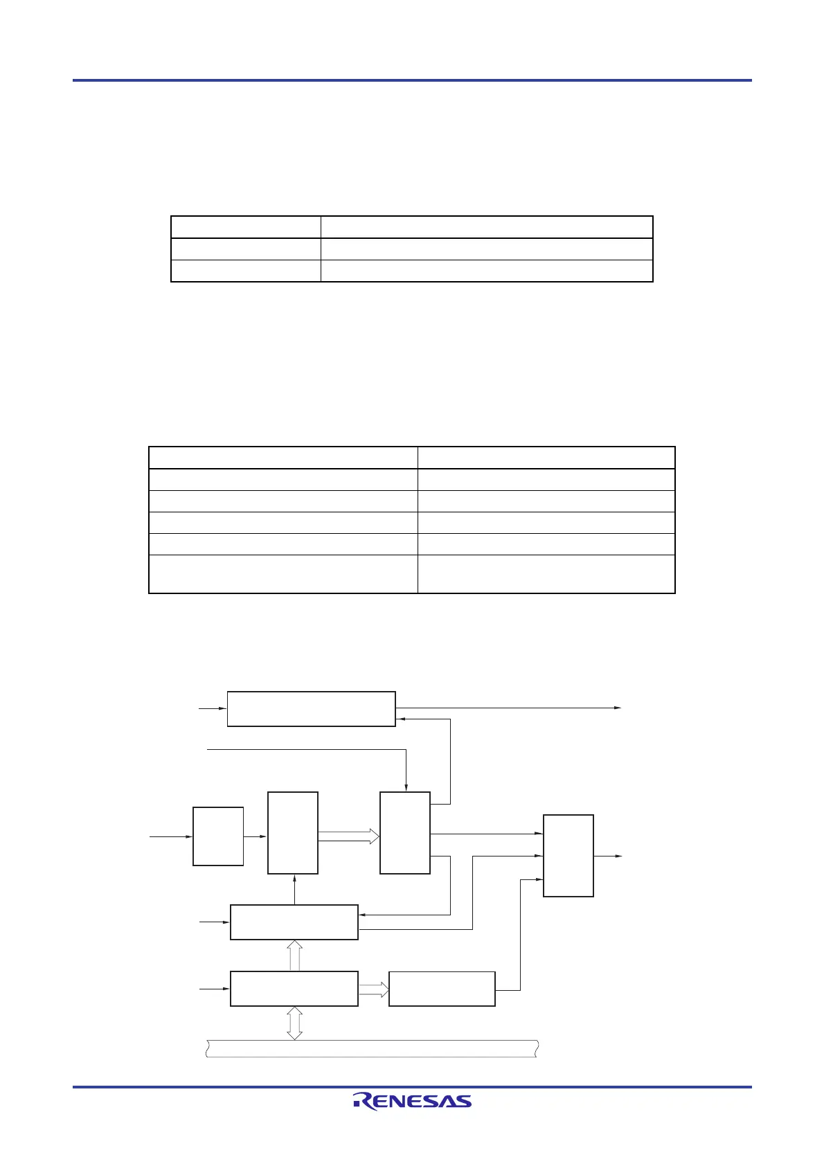
Figure 11-1. Block Diagram of Watchdog Timer
f
WDT
WDTON of option
byte (000C0H)
WDTINT of option
byte (000C0H)
Interval time controller
(Count value overflow time × 3/4)
Interval time interrupt
WDCS2 to WDCS0 of
option byte (000C0H)
Clock
input
controller
Internal
counter
(17 bits)
Selector
Overflow signal
Reset
output
controller
Internal reset signal
Count clear
signal
Window size
decision signal
Window size check
Watchdog timer enable
register (WDTE)
Write detector to
WDTE except ACH
Internal bus
WINDOW1 and
WINDOW0 of option
byte (000C0H)
fWDT/2
6
to fWDT/2
16
 Loading...


