RL78/F13, F14 CHAPTER 8 TIMER RD
R01UH0368EJ0210 Rev.2.10 639
Dec 10, 2015
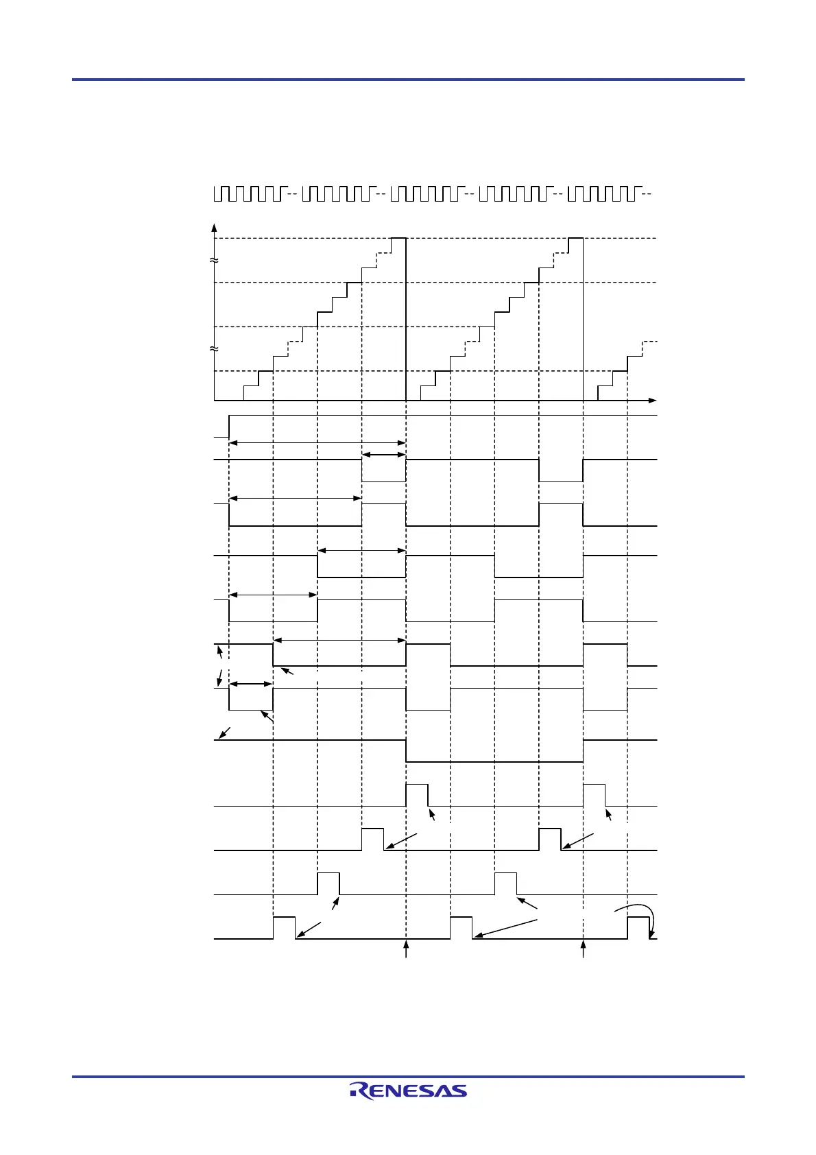
(1) Operation Example
Figure 8-56. Operation Example in Reset Synchronous PWM Mode
m
n
p
m + 1
q
m - n
n + 1
m - q
m - p
p + 1
q+1
0000H
Count source
Value in TRD0 register
TSTART0 bit in
TRDSTR register
TRDIOB0 output
TRDIOD0 output
TRDIOA1 output
TRDIOC1 output
TRDIOB1 output
TRDIOD1 output
TRDIOC0 output
IMFA bit in
TRDSR0 register
IMFB bit in
TRDSR0 register
IMFA bit in
TRDSR1 register
IMFB bit in
TRDSR1 register
Remark
i = 0 or 1
m: Value set in TRDGRA0 register
n: Value set in TRDGRB0 register
p: Value set in TRDGRA1 register
q: Value set in TRDGRB1 register
The above diagram applies under the following condition :
Bits OLS1 and OLS0 in the TRDFCR register are set to 0 (initial output level is high, active level is low).
Set to 0 by a program
Set to 0 by a program
Set to 0 by a program
Initial output is high
Active level is low
Active level is low
Initial output is high
Time
Set to 0 by a program
Transfer from the buffer register to the
general register during buffer operation
Transfer from the buffer register to the
general register during buffer operation
 Loading...


