Do you have a question about the Rigol DS4024E and is the answer not in the manual?
| Bandwidth | 200 MHz |
|---|---|
| Channels | 4 |
| Vertical Sensitivity | 1 mV/div to 10 V/div |
| Vertical Resolution | 8 bits |
| Max Input Voltage | 400 V (DC + AC peak) |
| Display | 8 inch TFT LCD (800 x 480 pixels) |
| Input Impedance | 1 MΩ |
| Trigger Modes | Edge, Pulse, Video |
| Timebase Range | 2 ns/div to 50 s/div |
| Interfaces | USB, LAN |
| Input Coupling | AC, DC, GND |
| Power Supply | 100-240 VAC, 45-440 Hz |
| Sample Rate | 2 GSa/s (Real-time) |
Provides a summary of essential safety precautions to prevent injury and damage.
Specifies requirements for adequate ventilation to ensure proper cooling and prevent overheating.
Details the initial inspection of packaging, instrument, and accessories.
Guides on preparing the oscilloscope for operation, including cover removal and leg adjustment.
Explains how to connect the oscilloscope to the AC power source.
Provides instructions for connecting passive, active, and Tek probes to the oscilloscope.
Details how to inspect and compensate passive probes before measurement.
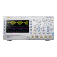
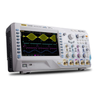
Provides a labeled diagram and description of the oscilloscope's front panel controls.
Details the connectors and ports located on the rear panel of the oscilloscope.
Explains the functions of various controls on the front panel, including VERTICAL and HORIZONTAL.
Describes the main elements and layout of the oscilloscope's user interface.
Explains how to enable or disable the input channels (CH1-CH4) for signal acquisition.
Details how to adjust the vertical scale (V/div) for waveform amplitude display.
Guides on adjusting the vertical position of the waveform on the screen.
Explains how to set channel coupling modes (DC, AC, GND) to filter signals.
Describes setting the bandwidth limit to reduce display noise.
Provides information on setting up and configuring connected probes.
Details the settings and functions specific to passive probes.
Explains the settings and calibration procedures for active probes.
Covers the settings and compatibility for Tektronix probes.
Explains how to set the input impedance (1 MΩ or 50 Ω) to reduce circuit load.
Explains how to calibrate the zero offset by setting the probe cable delay time.
Details how to adjust the horizontal time base (s/div) for waveform display.
Guides on adjusting the horizontal position (trigger point) of the waveform.
Explains how to select time base modes like Y-T, X-Y, and Roll.
Describes how to enable or disable delayed sweep for waveform detail magnification.
Explains how to set the horizontal reference for waveform expansion/compression.
Explains the sampling process and factors affecting sample rate.
Details how to select acquisition modes like Normal, Average, Peak Detect, High Resolution.
Explains how to set the memory depth for waveform data storage.
Explains how to select trigger sources from channels, EXT, or AC Line.
Details how to adjust the trigger level for stable waveform triggering.
Explains the available trigger modes: Auto, Normal, and Single.
Describes trigger coupling settings (DC, AC, LF Reject, HF Reject) to filter signal components.
Explains setting the holdoff time to prevent re-triggering within a specified period.
Details how to configure edge triggers based on signal slope and level.
Explains setting pulse triggers based on positive or negative pulse width.
Describes runt trigger settings for pulses that fail to cross specific trigger levels.
Covers setting Nth edge triggers based on the number of edges and idle time.
Explains slope trigger settings based on specified positive or negative slope with time.
Details video trigger settings for capturing complex video signal waveforms.
Explains pattern trigger configuration for logical combinations of channel states.
Guides on performing various math operations like addition, subtraction, FFT, and digital filters.
Explains how to perform automatic measurements of waveform parameters.
Details using cursors to measure parameters like voltage, time, and frequency.
Details defining the test mask using screen or cursor regions.
Guides on controlling the oscilloscope remotely via USB, including driver installation.
Explains controlling the oscilloscope remotely via LAN using Ultra Sigma software.
Details controlling the oscilloscope remotely via GPIB using a USB-GPIB converter.