100 Rockwell Automation Publication 750-IN118A-EN-P - May 2021
Chapter 4 Power Wiring
Terminal Lug Connections
Different versions of terminal lug connection hardware are used for various
connections in some configured input bays and configured output bays. One
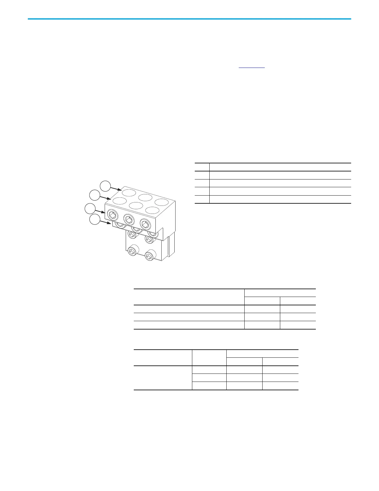
example of a terminal lug is shown in Figure 98
. Terminal lug connection
hardware varies in how many cables can be connected and what size of cables
can be connected. For details about specific terminal lug connections, see the
following tables. Make a terminal lug connection as follows:
1. Strip only enough insulation off the end of the power cable for the bare
cable to get all the way down the terminal to the point where it is in front
of the set screw for that terminal.
2. Insert the bare cable all the way down the terminal to the point where it is
in front of the set screw for that terminal.
3. Tighten the set screw for that terminal to the torque listed in one of the
following tables, securing the cable.
Figure 98 - Example Terminal Lug
Item Description
1 Back row of cable terminals, secured by bottom row of cable set screws
2 Front row of cable terminals, secured by top row of cable set screws
3 Top row of cable set screws
4 Bottom row of cable set screws
Table 13 - Frame 8 Terminal Lug Locations and Torques
Location of Terminal Lug Connection
Tightening Torque for Set Screw
N•m lb•in
Configured input bay input protection circuit breaker 43 380
Configured input bay input protection fuse busbars 42 375
Configured output bay contactor 42 375
Table 14 - Frame 9 Terminal Lug Locations and Torques
Location of Terminal Lug
Connection
Circuit Breaker
Frame Size
(1)
(1) To find the frame size of your circuit breaker, find the catalog number on the circuit breaker.
This catalog number begins with “140G” followed by the circuit breaker frame size, “-M”, “-N”,
or “-R”. Use the corresponding torque value.
Tightening Torque for Set Screw
N•m lb•in
Configured input bay input
protection circuit breaker
M43380
N43380
R57505

 Loading...


