62 Rockwell Automation Publication 750-IN118A-EN-P - May 2021
Chapter 3 Mechanical and Electrical Installation
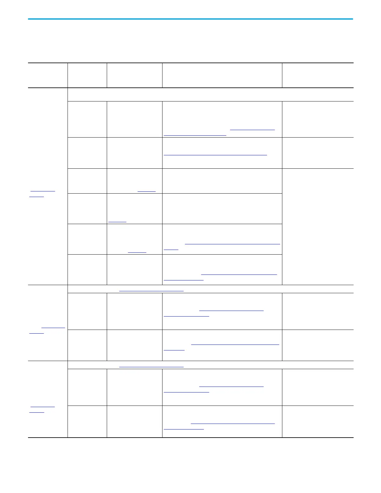
Frame 9 Electrical Connections
Table 9 - Frame 9 Configured Bays - Bay to Bay, Bay to Customer Power Source, and Bay to Customer Motor Electrical Connections Made
During Installation
(1)
Configured Bay
Connection
Location On
Configured Bay
Item Connected to
Configured Bay
Material Used to Make Connection
When Product Arrives to
Customer, Location and State of
Materials Used to Make
Connection
Configured input
bay, control-only
(Figure 70 on
page 76)
No power or ground connections are made to the control-only configured input bay during installation. Customer AC power source and ground are
connected to the drive input bay.
Configured bay
control connectors
in configured input
bay
Configured bay control
connectors in configured
output bay
Each configured bay control connector in the configured
input bay connects to a configured bay control connector in
the configured output bay. The connection hardware for each
of these connections is a bundle of 16 AWG control cables,
with connectors on both ends. See Configured Bay Control
Connection Hardware on page 88.
• Inside the drive bays
• Must be connected to both the
configured input bay and
configured output bay during
installation
PE ground bar Drive PE ground bar PE Ground Bar Splice Connection Hardware on page 84
• Connected to configured input
bay PE ground bar
• Must be connected to drive input
bay PE ground bar during
installation
TB1, terminal 1,
+24V DC
Drive input bay TB5 (+24V
DC). See 24V DC Terminal
Block and Control Bus
Connections in 750-IN100
.
Control cable - 16 AWG
• Inside the configured input bay
• Connected to the configured
input bay
• Must be connected to the drive
input bay during installation
TB1, terminal 5,
-24V DC
Drive input bay TB5
(Common). See the 24V DC
Terminal Block and Control
Bus Connections section in
750-IN100
.
Control cable - 16 AWG
PB3 (drive disable
push button)
terminals 21 and 22
In drive input bay, control
pod, main control board,
TB1 (I/O terminal block). See
the Main Control Board
section in 750-IN100
.
Control cables - 16 AWG, connected to one plug connector that
connects to the TB1 socket connector on the main control
board. See Drive Main Control Board Connection Hardware on
page 87.
Multiple
connection
locations. See the
schematic for the
full list.
22-Series I/O option module
inside control pod inside
drive input bay
Control cables - 16 AWG, connected to two plug connectors
that connect to the socket connectors on the 22-Series I/O
option module. See 22-Series I/O Option Module Connection
Hardware on page 87.
Configured input
bay with fuses, top
entry (Figure 71 on
page 77)
All connections in frame 9 Configured input bay, control-only
AC power input
extruded busbars
Customer AC power source
Power cables with Barrel Lug to L-Bracket to Busbar
Connections on page 98
• The L-brackets are connected to
the busbar.
• The cable is provided by the
customer, and must be
connected to the L-brackets
during installation.
AC power output
busbars
Drive AC power input
busbar
Flexibars. See Flexibar Flexible Busbar Connection Hardware
on page 86.
• Shipped in a box that comes with
the configured input bay
• Must be connected to both the
configured input bay and the
drive input bay during installation
Configured input
bay with fuses,
bottom entry
(Figure 72 on
page 78)
All connections in frame 9 Configured input bay, control-only
AC power input
busbars
Customer AC power source
Power cables with Barrel Lug to L-Bracket to Busbar
Connections on page 98
• The L-brackets are connected to
the busbar.
• The cable is provided by the
customer, and must be
connected to the L-brackets
during installation.
AC power output
busbars
Drive AC power input
busbars
Power cables with single bolt barrel lug connections provided
standard. See Barrel Lug to Drive Input Busbar Connection
Hardware on page 86.
• Inside the configured input bay
• Connected to the configured
input bay
• Must be connected to the drive
during installation

 Loading...


