84 Rockwell Automation Publication 750-IN118A-EN-P - May 2021
Chapter 3 Mechanical and Electrical Installation
Bay to Bay Connection
Hardware
This section covers the types of hardware that are used to electrically connect
bays when they are shipped as part of separate shipping sections.
For drawings showing where to make these connections, see Component and
Connection Locations on page 64. For information on which type of hardware
is used for each connection, and the state and location it is in when it arrives to
the customer, see Electrical Connections Made to Each Configured Bay During
Installation on page 61.
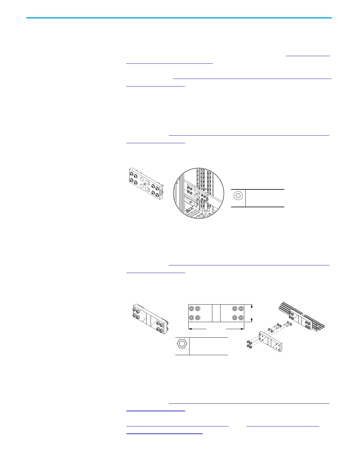
PE Ground Bar Splice Connection Hardware
To determine if you must make a connection using this hardware during
installation, see Electrical Connections Made to Each Configured Bay During
Installation on page 61. If two bays that have a PE ground bar are joined
together during installation, use this hardware to connect the PE ground bars.
Figure 80 - PE Ground Bar Splice Connection Hardware
AC Busbar Splice Connection Hardware
To determine if you must make a connection using this hardware during
installation, see Electrical Connections Made to Each Configured Bay During
Installation on page 61. This hardware is used to make the power connection
from the drive power bay to some types of configured output bay.
Figure 81 - AC Busbar Splice Connection Hardware
Terminal Lug Connection Hardware
To determine if you must make a connection using this hardware during
installation, see Electrical Connections Made to Each Configured Bay During
Installation on page 61. Terminal lug connections are used for some bay to bay
connections and for some customer power source and motor connections. See
Terminal Lug Connections on page 100
in the Customer Input Power and
Motor Connection Hardware section.
85 mm
(3.3 in.)
268.5 mm
(10.6 in.)
M10
15 mm
38 N•m (336 lb•in)

 Loading...


