40 Rockwell Automation Publication 750-IN118A-EN-P - May 2021
Chapter 2 Prepare for Installation
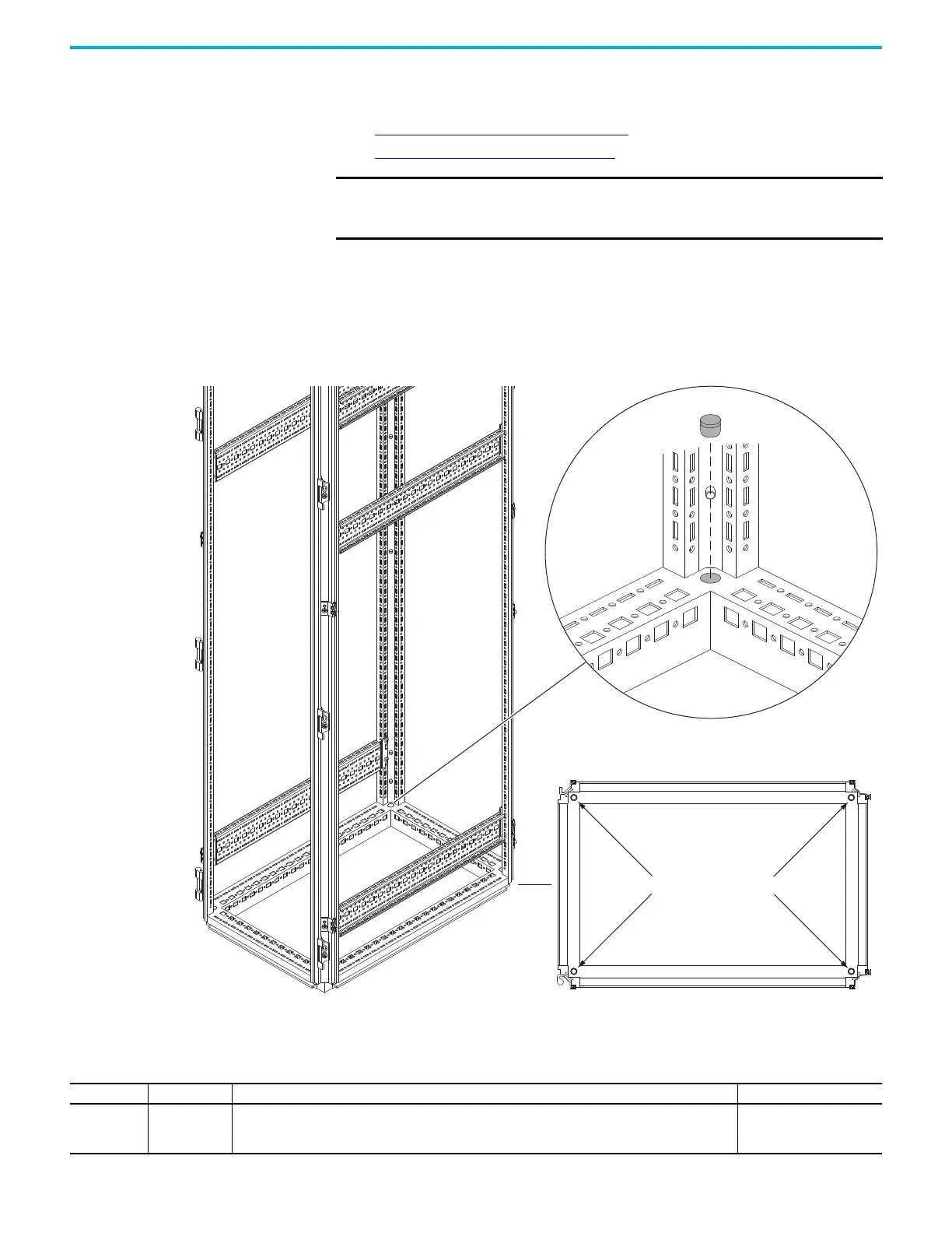
Floor Mounting Options Use one of the following types of mounting hardware between the bay and the
floor:
• Rittal Base/Plinth System on page 41
• Structural Steel System on page 43
All mounting options use the mounting holes that are located at the corners of
the base of the bay. All four mounting holes must be used to secure the bay
properly. Remove the debris plug when using mounting hardware that must
pass through the mounting hole.
Figure 39 - Typical Bay Mounting Holes
Recommended Mounting Fasteners
IMPORTANT
Bays must be mounted to the floor using one of these floor mounting
options between the bays and the floor. Bays cannot be mounted
directly to the floor.
Four bay mounting holes
Debris plug
Frame Size Fastener Size Usage Notes
Frames 8…9 M12 (0.5 in.)
• Secure the bay to the mounting system (corner base/plinth system or structural steel) by threading the
fastener into the bay mounting hole.
• Secure the mounting system (corner base/plinth system or structural steel) to the mounting surface.
Property Class 8.8 or better
(Grade 5 or better)

 Loading...


