Rockwell Automation Publication 750-IN118A-EN-P - May 2021 59
Chapter 3 Mechanical and Electrical Installation
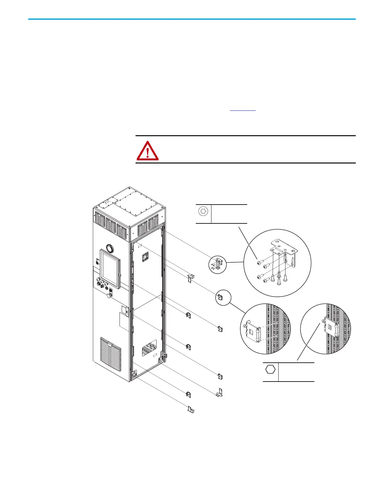
Internal Corner Brackets and Frame Clamps
When two bays are joined with internal corner brackets and frame clamps,
four internal corner brackets and six frame clamps are used to join the bays.
Your product may include additional frame clamps, which can be used as spare
parts. To install the bay joining hardware, use the following procedure.
1. Make sure that the two sides of the joining are aligned, level, and pushed
together tightly.
2. Attach the interior corner brackets to the four interior corners of the
mating surface as shown in Figure 55
.
3. Place and tighten the frame clamps, clamping the side frames of the bays
together.
Figure 55 - Joining Bays with Interior Corner Brackets and Frame Clamps
ATTENTION: Do not attempt to lift bays that are joined with this hardware.
–
–
9.0 N•m (79 lb•in)
M5.5
T20
4.7 N•m (42 lb•in)

 Loading...


