Rockwell Automation Publication 750-IN118A-EN-P - May 2021 95
Chapter 4 Power Wiring
Shield Termination - SHLD
The Shield terminal provides a grounding point for the motor cable shield. It
must be connected to an earth ground by a separate continuous lead. Connect
the motor cable shield to this terminal on the drive (drive end) and the motor
frame (motor end). Use a shield terminating conduit fitting to connect shield
to this terminal. See Wiring and Grounding Guidelines for Pulse Width
Modulated (PWM) AC Drives, publication DRIVES-IN001
.
RFI Filter Grounding
Using an optional RFI filter may result in relatively high ground leakage
currents. Therefore, the filter must only be used in installations with
grounded AC supply systems and be permanently installed and solidly
grounded (bonded) to the building power distribution ground. Be sure that the
incoming supply neutral is solidly connected (bonded) to the same building
power distribution ground. Grounding must not rely on flexible cables and
should exclude any form of plug or socket that would permit inadvertent
disconnection. Some local codes may require redundant ground connections.
The integrity of all connections should be periodically checked. See the
instructions supplied with the filter.
Power Cable Specifications Various cable types can be used as input power cables and motor cables for
PowerFlex 755T Drives Configured to Order Program installations. For an in-
depth discussion of cable types, including a table of maximum motor cable
lengths, see the Wiring and Grounding Guidelines for Pulse Width Modulated
(PWM) AC Drives, publication DRIVES-IN001
.
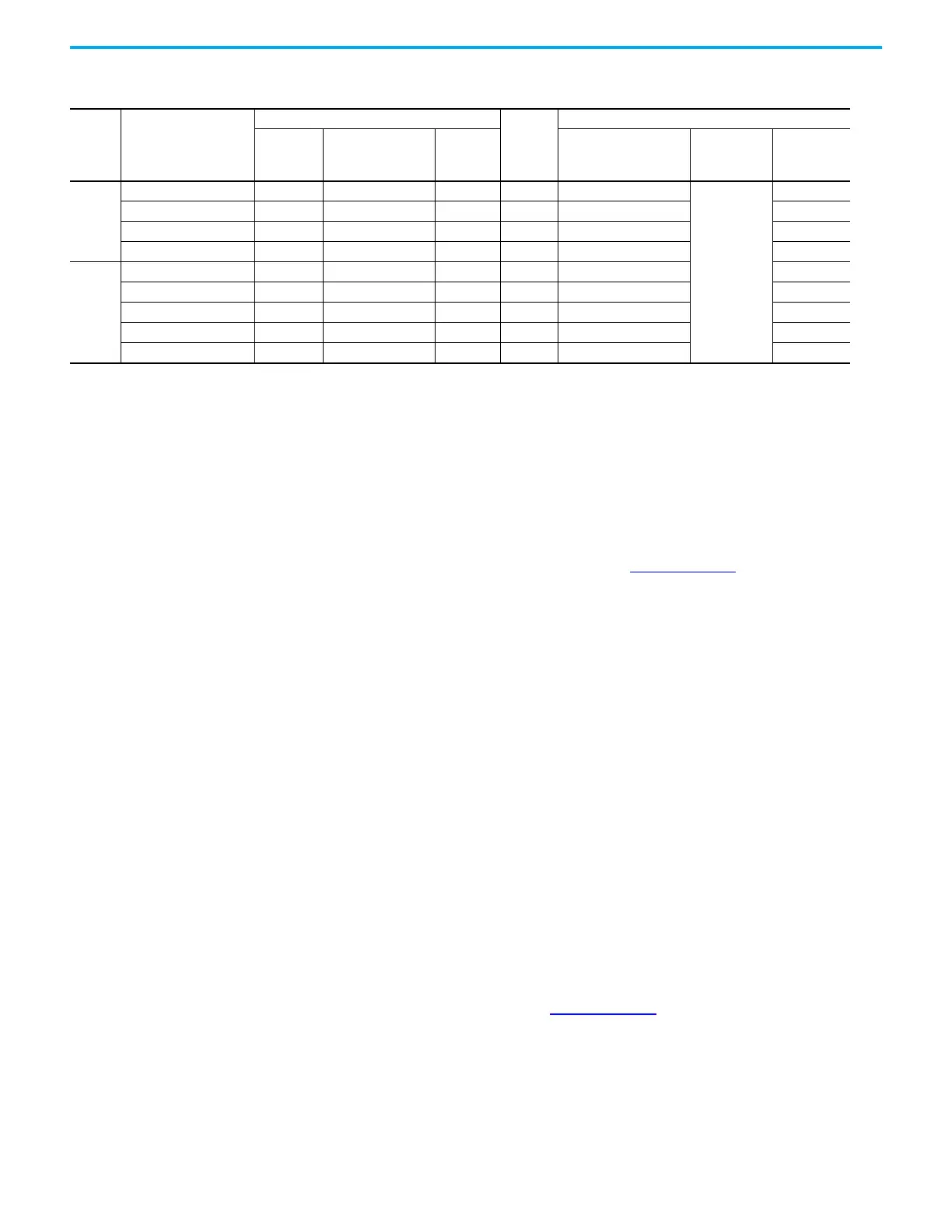
Table 10 - Grounding Clamps
Frame Bay
Grounding Clamp Specifications
Quantity
Shipped
with Bay
Ordering Additional Clamps
Wire Size
Range ISO
(mm
2
)
Wire Size Range
AWG/MCM
Tightening
Torque
N•m (lb•in)
Rockwell Automation Kit
Catalog Number
Manufacturer
Manufacturer
Part Number
8
Configured input bay 2.5…16 14…6 AWG 3 (27) 3 SK-RM-GRNDCLMP-16
Rittal
3456500
Configured output bay 2.5…16 14…6 AWG 3 (27) 3 SK-RM-GRNDCLMP-16 3456500
Configured input bay 70…185 2/0 AWG…350 MCM 15 (133) 3 SK-RM-GRNDCLMP-185 3459500
Configured output bay 70…185 2/0 AWG…350 MCM 15 (133) 4 SK-RM-GRNDCLMP-185 3459500
9
Configured input bay 2.5…16 14…6 AWG 3 (27) 3 SK-RM-GRNDCLMP-16 3456500
Configured output bay 2.5…16 14…6 AWG 3 (27) 3 SK-RM-GRNDCLMP-16 3456500
Configured input bay 70…185 2/0 AWG…350 MCM 15 (133) 6 SK-RM-GRNDCLMP-185 3459500
Configured output bay 70…185 2/0 AWG…350 MCM 15 (133) 8 SK-RM-GRNDCLMP-185 3459500
Configured output bay 16…50 6…1 AWG 8 (71) 2 SK-RM-GRNDCLMP-50 3457500

 Loading...


