Rockwell Automation Publication 750-IN118A-EN-P - May 2021 37
Chapter 2 Prepare for Installation
Minimum Clearances and Access Requirements
Consider the following clearance and access requirements when choosing the
installation location of your product.
Overhead Clearance
Overhead clearance is the minimum space that is required above the bays to
allow for servicing of the roof exhaust vents. This clearance varies depending
on which type of bay is used, IP21, UL Type 1, or IP54, UL Type 12. The overhead
clearance of the entire lineup of bays together is determined by the overhead
clearance of the drive main power bay because it has the tallest roof exhaust
vents.
Airflow Clearances and Considerations
Make sure that the air-intake and exhaust locations are not obstructed. Airflow
through the bay is required to maintain proper cooling. Make sure that air
temperature around the bays does not exceed the ambient temperature
specification in the Environmental Specifications on page 34
.
Some airflow examples are provided in Figure 36
and Figure 37 on page 38. The
vents below the center of the bay are air-intake locations (white arrows) and
the vents above the center of the bay are air exhaust locations (black arrows).
Regularly inspect and replace the filter media at air-intake and exhaust
locations to maintain proper airflow and cooling. For filter maintenance
schedules, see the following:
• For configured bay filters, see Service and Maintenance on page 111
.
• For drive bay filters, see the PowerFlex 750-Series Products with
TotalFORCE Control Hardware Service Manual, publication 750-TG100
.
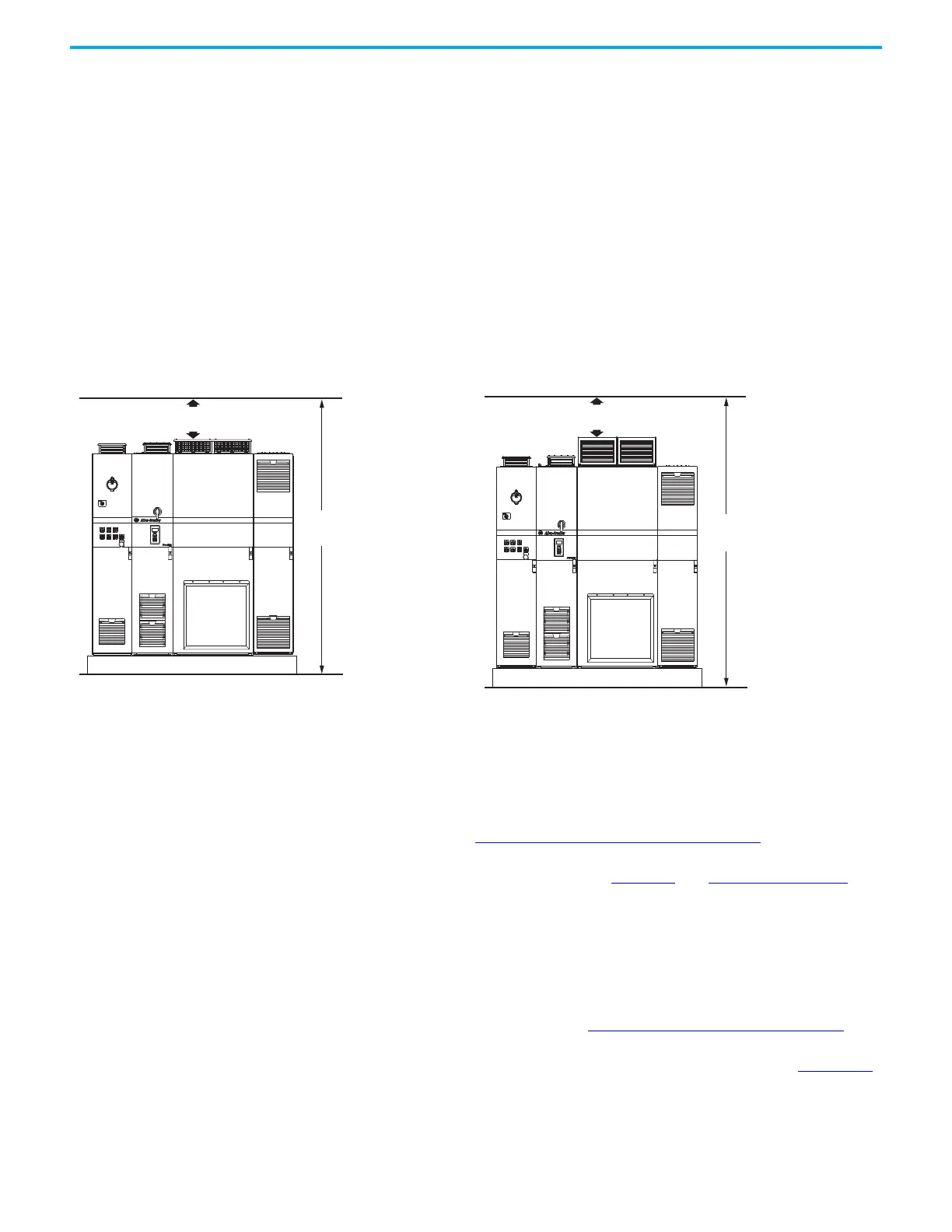
Figure 34 - Overhead Clearance for Frame 8 and 9, IP21, UL Type 1
Enclosures (Frame 8 bays shown)
Figure 35 - Overhead Clearance for Frame 8 and 9, IP54, UL Type 12
Enclosures (Frame 8 bays shown)
200 mm (7.9 in.)
(95.8 in.)
100 mm (3.9 in.) mounting hardware
2641 mm
250 mm (9.8 in.)
(104.0 in.)
100 mm (3.9 in.) mounting hardware

 Loading...


