110 Rockwell Automation Publication 750-IN118A-EN-P - May 2021
Chapter 4 Power Wiring
Bypass Contactor Precaution
A bypass contactor configuration is not available as a configured to order
option in the PowerFlex 755T Drives Configured to Order Program. If you
supplied a bypass contactor system, setup may involve modification to the
configured bays. The following precautions apply.
Install Components that
were Removed During
Installation
Install any components that were removed to facilitate installation. These
components include all components that were removed in Prepare Bay
Interiors for Installation on page 48. Install removed components as follows:
1. Review the Product Advisories on page 11
.
2. Remove power from the system. See Remove Power from the System on
page 117.
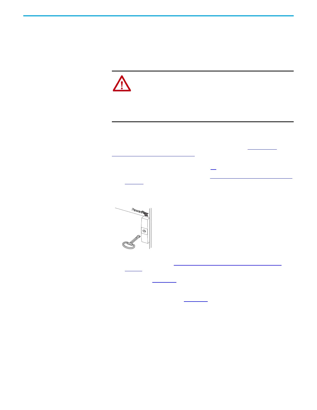
3. Use the double-bit key that is provided to open the bay doors.
Figure 99 - Unlocking the Bay Door
4. Install the protective touch guards. To install the guards in the
configured bays. See Remove or Install Protective Touch Guards on
page 49. To install the guards in the drive bays, see the PowerFlex 750-
Series Products with TotalFORCE Control Installation Instructions,
publication
750-IN100.
5. Install any components that were removed from the drive. See the
PowerFlex 750-Series Products with TotalFORCE Control Installation
Instructions, publication
750-IN100.
ATTENTION: An incorrectly applied or installed bypass system can result in
component damage or reduction in product life. The most common causes
are:
• Wiring AC line to drive output or control terminals
• Improper bypass or output circuits, which are not approved by Rockwell
Automation
• Output circuits that do not connect directly to the motor
Contact Rockwell Automation for assistance with application or wiring.

 Loading...


