Rockwell Automation Publication 750-IN118A-EN-P - May 2021 121
Chapter 5 Service and Maintenance
IP21/IP54 Door Vent
To replace the IP21/IP54 door vent with no fan included, use the following
procedure. This procedure applies to multiple types door vents, and some
exhaust hood vents. For the catalog number of the replacement part for your
product, see Replacement Parts on page 111
.
1. Review Product Advisories on page 11
.
2. Remove power from the system. See Remove Power from the System on
page 117.
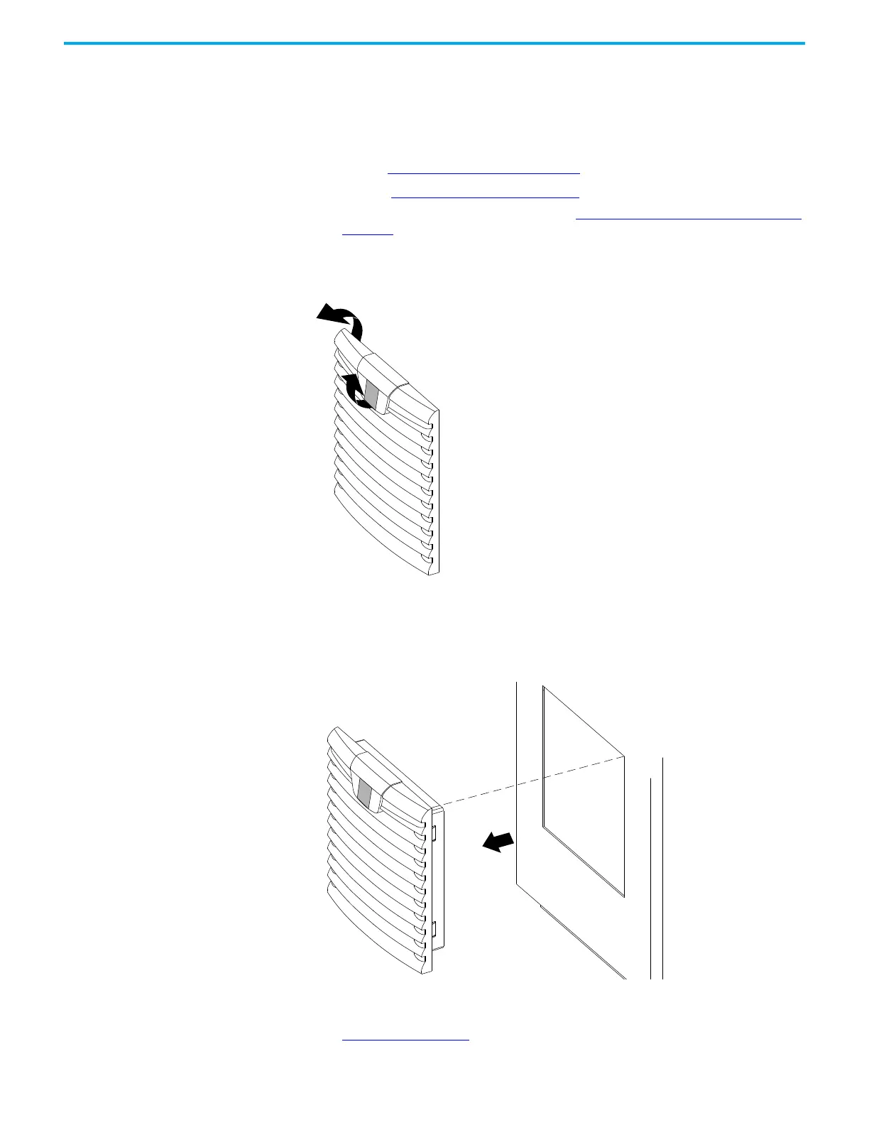
3. Lift the tab on the top center of the vent cover and open the vent cover.
Figure 108 - Lifting the Vent Cover Release Tab and Opening the Vent Cover
4. Remove the screws that secure the vent to the bay door. These screws are
at the corners of the vent.
5. Remove the vent from the bay door.
Figure 109 - Removing the Vent
6. Insert the new vent into the bay door.
7. Install the screws that secure the vent to the bay door. For torques, see
Table 23 on page 118
.

 Loading...


