Rockwell Automation Publication 750-IN118A-EN-P - May 2021 87
Chapter 3 Mechanical and Electrical Installation
Drive Main Control Board Connection Hardware
To determine if you must make a connection using this hardware during
installation, see Electrical Connections Made to Each Configured Bay During
Installation on page 61. This hardware is used to connect the configured input
bay drive disable push button to the main control board in the control pod in
the drive input bay.
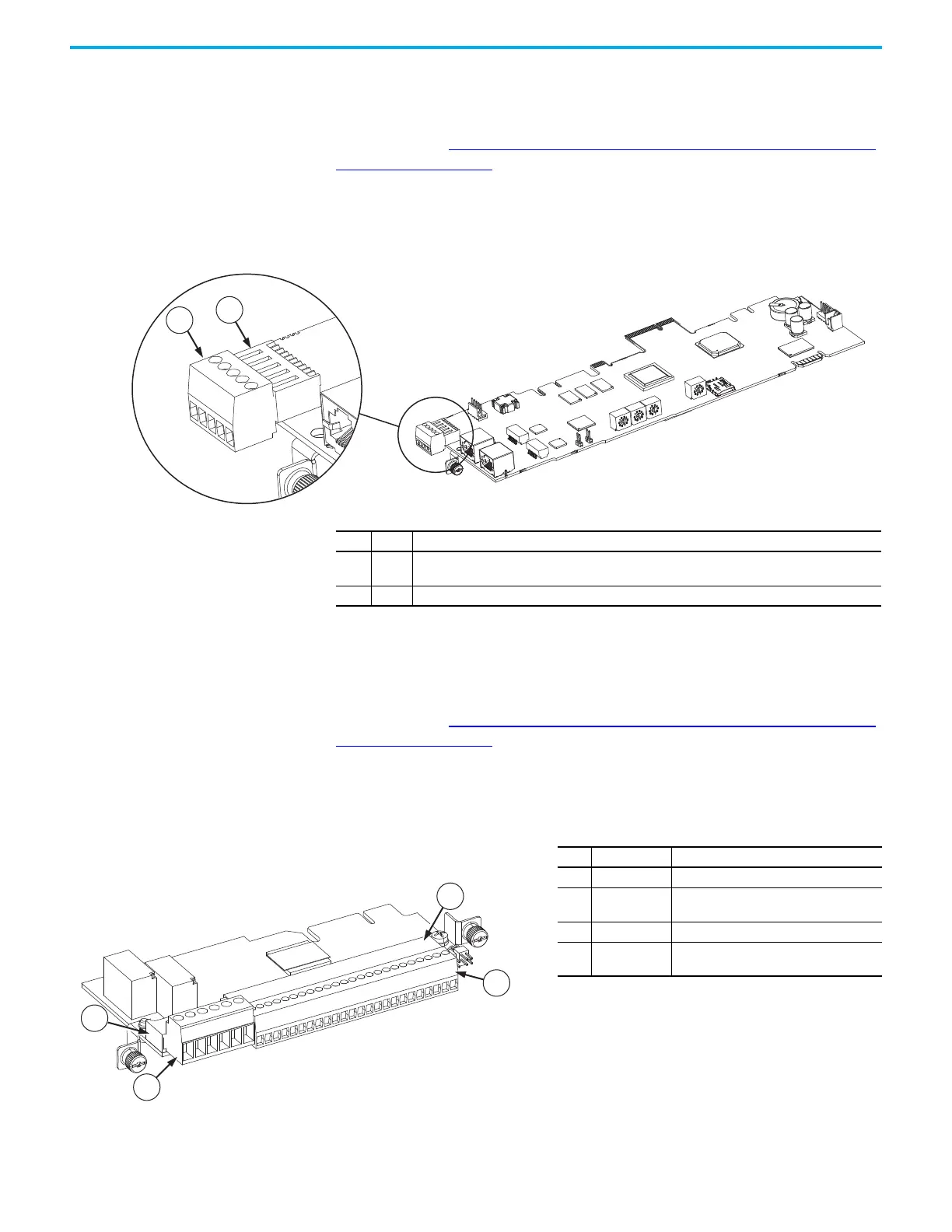
Figure 86 - Drive Disable Push Button to Main Control Board Connection Hardware
22-Series I/O Option Module Connection Hardware
To determine if you must make a connection using this hardware during
installation, see Electrical Connections Made to Each Configured Bay During
Installation on page 61. This hardware is used to connect various devices in the
configured input bay to the 22-Series I/O Option Module in the control pod in
the drive input bay. For a full list of all devices that are connected to the module
with these connections, see the electrical schematic that came with your
product.
Item Name Description
1TB1
Drive disable push button plug connector, has two 16 AWG wires connected. Must connect to item
2 during installation.
2 TB1 Input/output terminal block socket connector
Figure 87 - 22-Series I/O Option Module Connection Hardware
Item Identification Description
1 TB2 I/O module output connector plug
2TB2
I/O module output connector socket. Must
connect to item 1 during installation.
3 TB1 I/O module input connector plug
4TB1
I/O module input connector socket. Must
connect to item 3 during installation.

 Loading...


