Rockwell Automation Publication 750-IN118A-EN-P - May 2021 61
Chapter 3 Mechanical and Electrical Installation
Electrical Connections
Made to Each Configured
Bay During Installation
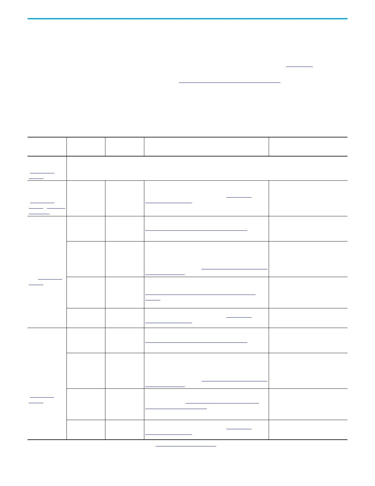
This section provides a summary of the electrical connections that must be
made to each configured bay during installation, including connections to
other bays and connections to customer power source and motor. Make the
connections in this section as described in PowerFlex 755T Drives Configured
to Order Program Installation Instructions, publication 750-IN118
. This
section does not include all grounding connections. For grounding
connections, see Grounding Requirements on page 94
.
Frame 8 Electrical Connections
Table 8 - Frame 8 Configured Bays - Bay to Bay, Bay to Customer Power Source, and Bay to Customer Motor Electrical Connections Made
During Installation
(1)
Configured Bay
Connection
Location On
Configured Bay
Item Connected to
Configured Bay
Material Used to Make Connection
When Product Arrives to Customer,
Location and State of Materials Used
to Make Connection
Configured input
bay, control-only
(Figure 58 on
page 66)
No connections are made to the control-only configured input bay during installation. Customer AC power source and ground are connected to the
drive input bay.
Configured input
bays with input
protection
(Figure 59 on
page 67…Figure 62
on page 70)
AC input power
terminals
Customer AC
power source
Power cables, terminal lug connection. See Terminal Lug
Connections on page 100.
• Provided by the customer
• Must be connected to configured bay
during installation
Configured output
bay with contactor
only, top or bottom
exit (Figure 65 on
page 72)
PE ground bar
Drive power bay PE
ground bar
PE Ground Bar Splice Connection Hardware on page 84
• Connected to the configured output
bay PE ground bar
• Must be connected to the drive power
bay PE ground bar during installation
Configured bay
control connectors
in configured
output bay
Configured bay
control connectors
in configured input
bay
Each configured bay control connector in the configured input
bay connects to a configured bay control connector in the
configured output bay. The connection hardware for each of
these connections is a bundle of 16 AWG control cables, with
connectors on both ends. See Configured Bay Control Connection
Hardware on page 88.
• Inside the configured input bay and
drive bays
• Connected to the configured input bay
• Must be connected to configured
output bay during installation
Contactor input
terminals
Drive power bay AC
power output
busbar
Power cables with barrel lugs connect to drive output busbar. See
Barrel Lug to Drive Output Busbar Connection Hardware on
page 85.
• Inside the configured output bay
• Connected to the configured output
bay
• Must be connected to the drive during
installation
Contactor output
terminals
Customer motor
Power cables, terminal lug connection. See Terminal Lug
Connections on page 100.
• Provided by the customer
• Must be connected to the configured
output bay during installation
Configured output
bay with sine-wave
filter
(2)
and
contactor, top or
bottom exit
(Figure 67 on
page 73)
PE ground bar
Drive PE ground
bar
PE Ground Bar Splice Connection Hardware on page 84
• Connected to configured output bay
PE ground bar
• Must be connected to drive power bay
PE ground bar during installation
Configured bay
control connectors
in configured
output bay
Configured bay
control connectors
in configured input
bay
Each configured bay control connector in the configured input
bay connects to a configured bay control connector in the
configured output bay. The connection hardware for each of
these connections is a bundle of 16 AWG control cables, with
connectors on both ends. See Configured Bay Control Connection
Hardware on page 88.
• Inside the configured input bay and
drive bays
• Connected to the configured input bay
• Must be connected to configured
output bay during installation
Input terminals on
sine-wave filter
reactor
Drive AC power
output busbar
Braided busbars. See Braided Busbar to Drive Output Busbar
Connection Hardware on page 85.
• Inside the configured output bay
• Connected to the configured output
bay
• Must be connected to the drive during
installation
Contactor output
terminals
Customer motor
Power cables, terminal lug connection. See Terminal Lug
Connections on page 100.
• Provided by the customer
• Must be connected to the configured
output bay during installation
(1) Not all grounding connections included. For grounding connections, see Grounding Requirements on page 94.
(2) With a sine-wave filter, do not use a pulse width modulation (PWM) frequency less than 2 kHz.

 Loading...


