Rockwell Automation Publication 750-IN118A-EN-P - May 2021 85
Chapter 3 Mechanical and Electrical Installation
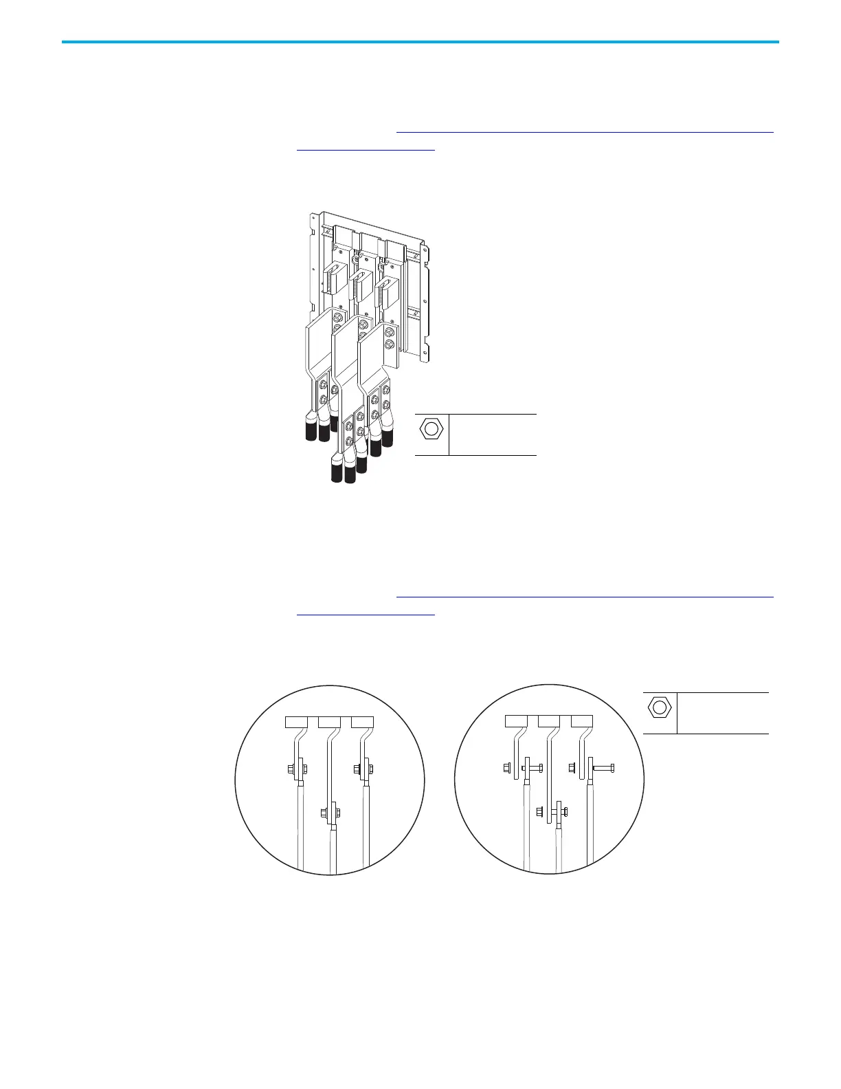
Barrel Lug to Drive Output Busbar Connection Hardware
To determine if you must make a connection using this hardware during
installation, see Electrical Connections Made to Each Configured Bay During
Installation on page 61. This hardware is used to make the power connection
from the drive power bay to some types of configured output bay.
Figure 82 - Barrel Lug Connections to Drive Output Busbars
Braided Busbar to Drive Output Busbar Connection Hardware
To determine if you must make a connection using this hardware during
installation, see Electrical Connections Made to Each Configured Bay During
Installation on page 61. This hardware is used to make the power connection
from the drive power bay to some types of configured output bay.
Figure 83 - Braided Busbar Connections to Drive Output Busbars
M10
19 mm
38 N•m (336 lb•in)
M10
40 mm
57 N•m (504 lb•in)

 Loading...


