EasyManuals Logo
Home>Rockwell Automation>DC Drives>Allen-Bradley PowerFlex 755T

Rockwell Automation Allen-Bradley PowerFlex 755T Installation Instructions

Rockwell Automation Allen-Bradley PowerFlex 755T
130 pages
To Next Page IconTo Next Page
To Previous Page IconTo Previous Page
Page #99 background imageLoading...
Page #99 background image
Rockwell Automation Publication 750-IN118A-EN-P - May 2021 99
Chapter 4 Power Wiring
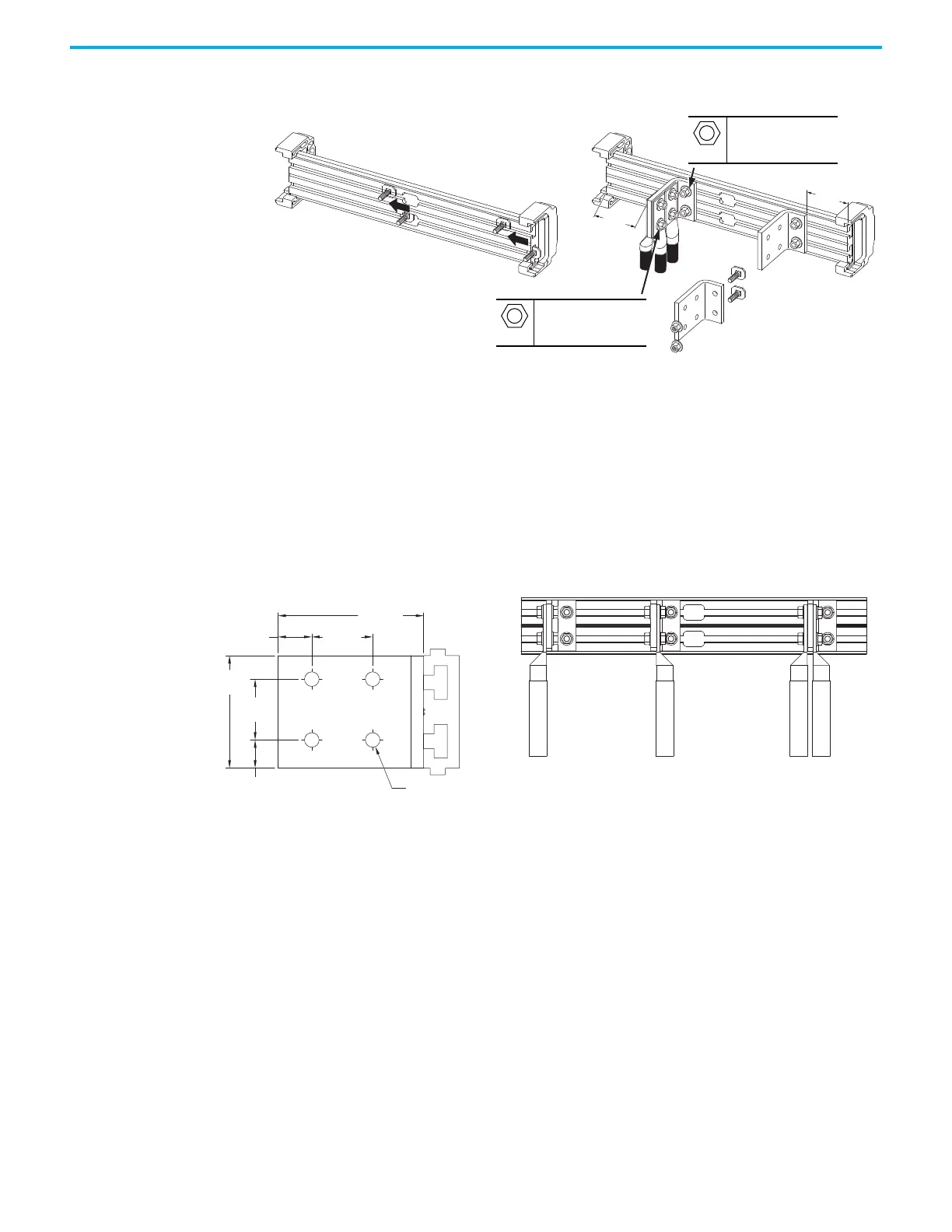
Figure 95 - Barrel Lug to Four Conductor L-Bracket to Busbar Connections with M10 and M12 Fasteners
Additional Power Terminal L-Brackets
If an application requires additional L-brackets, kit number 20-750-MLBRKT-
F8M is available. Each kit contains three L-brackets and mounting hardware.
When using mechanical barrel lugs, be sure to maintain adequate spacing to
adjacent wires, terminals, and other parts.
51 mm
(2 in.)
51 mm
(2 in.)
M12
19 mm
38.0 N•m (336 lb•in)
M10
15 mm
38.0 N•m (336 lb•in)
Figure 96 - L-Bracket Approximate Dimensions Figure 97 - Typical Barrel Lug Connection to L-Bracket Options
46.0 mm
(1.81 in.)
25.5 mm
(1.04 in.)
85.1 mm
(3.35 in.)
44.5 mm
(1.75 in.)
110.0 mm
(4.33 in.)
17.8 mm
(0.70 in.)
Ø 11.0 mm
(0.43 in.)
Left Side Right Side Both Sides - Up to four lugs.

Table of Contents

Other manuals for Rockwell Automation Allen-Bradley PowerFlex 755T

Questions and Answers:

Question and Answer IconNeed help?

Do you have a question about the Rockwell Automation Allen-Bradley PowerFlex 755T and is the answer not in the manual?

Rockwell Automation Allen-Bradley PowerFlex 755T Specifications

General IconGeneral
BrandRockwell Automation
ModelAllen-Bradley PowerFlex 755T
CategoryDC Drives
LanguageEnglish

Related product manuals