102 Rockwell Automation Publication 750-IN118A-EN-P - May 2021
Chapter 4 Power Wiring
Fuses Two categories of fuses are used in the configured input bays:
• Configured input bays with fuse input protection use Input Power Fuses
.
• All configured input bays use Control Fuses
.
Control Fuses
Input Power Fuses
In a configured input bay with AC line input protection using fuses, three
input power fuses are used, one for each phase. For fuse specifications, see the
following tables. For input power fuse locations, see Component and
Connection Locations on page 64.
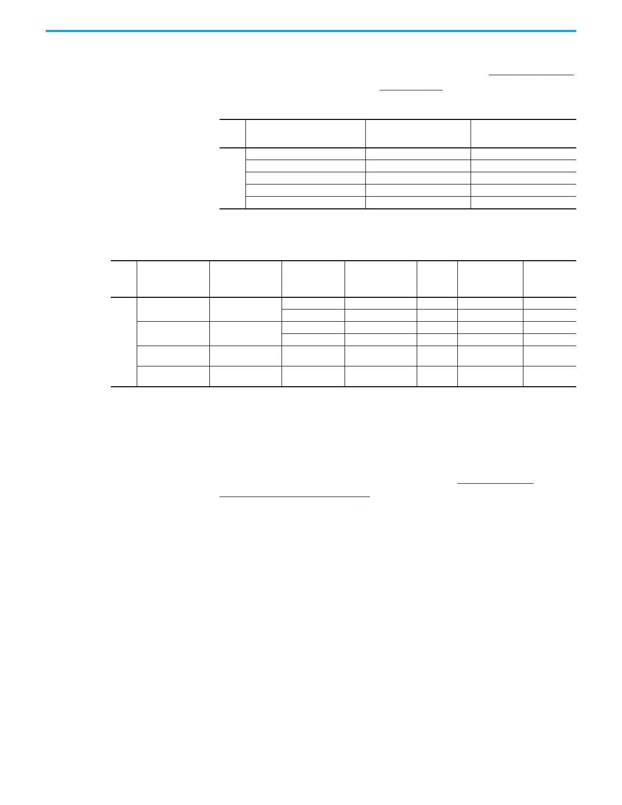
Table 15 - Fuse Schematic Symbols
Frame Fuse
Schematic Symbols in Configured
Input Bay with Fuse Input
Protection
Schematic Symbols in Configured
Input Bay with Control Only or
Circuit Breaker Input Protection
8, 9
Input Power Fuses FU1, FU2, FU3 —
Voltage Vision Fuses FU4, FU5, FU6 FU4, FU5, FU6
Control Transformer Primary Fuse FU7, FU8 FU7, FU8
Control Transformer Secondary Fuse 1 FU9 FU9
Control Transformer Secondary Fuse 2 FU10 FU10
Frame Fuse Schematic Symbol Input Voltage (V) Specification
Quantity
Included in
Configured
Input Bay
Manufacturer
Manufacturer
Part Number
8, 9
Voltage Vision Fuses FU4, FU5, FU6
400/480/600 Class CC - 600V, 1 A 3 Littelfuse Inc KLDR001.TXP
690 Class gG - 690V, 1 A 3 Mersen FR14GG69V1
Control Transformer
Primary Fuse
FU7, FU8
400/480/600 Class CC - 600V, 5 A 2 Littelfuse Inc KLDR005.TXP
690 Class gG - 690V, 4 A 2 Mersen FR14GG69V4
Control Transformer
Secondary Fuse 1
FU9 110/120 MIDGET - 250V, 6 A 1 Cooper Bussmann FNM-6
Control Transformer
Secondary Fuse 2
FU10 110/120 MIDGET - 250V, 7 A 1 Cooper Bussmann FNM-7

 Loading...


