Rockwell Automation Publication 750-IN118A-EN-P - May 2021 65
Chapter 3 Mechanical and Electrical Installation
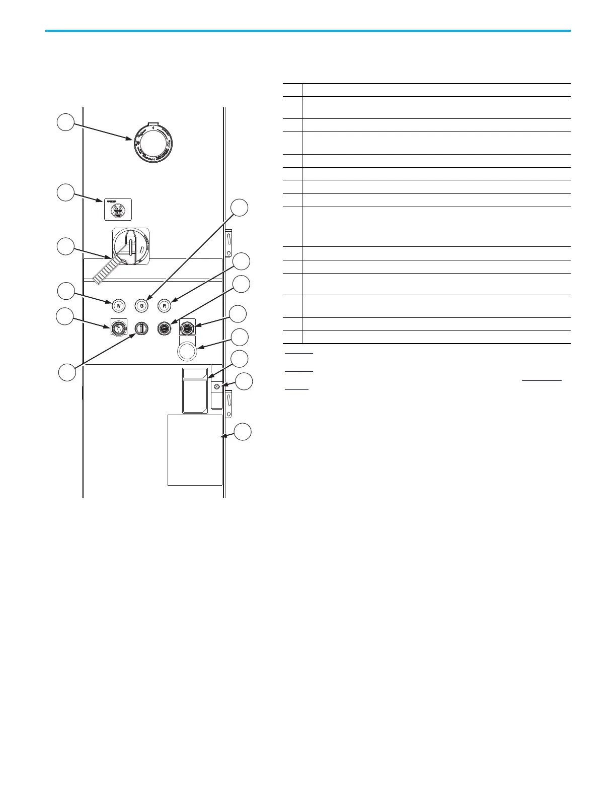
Frame 8 Component and Connection Locations
Figure 57 - Frame 8 All Possible Configured Input Bay Upper Door
External Components
Item Description
1
Infrared (IR) window - allows you to measure the temperature of the customer power
input connection using an infrared measuring device aimed through the window
2 Voltage vision - indicates the input voltage of each of the three phases
3
Circuit breaker lever - turns power to the drive ON/OFF at the circuit breaker (only
available with circuit breaker input protection)
4 Control power pilot light (white) - turns on when control power is on
5 Drive run pilot light (green) - turns on when the drive is running
6 Drive fault pilot light (red) - turns on when a drive fault occurs
7 Drive speed potentiometer - dial used to manually set motor speed
8
Hand-Off-Auto selector switch - selects between Hand mode, Off mode, and Auto
mode. In Hand mode, the drive is controlled using only the push buttons on the
configured input bay. In Off mode, the drive does not operate. In Auto mode, an
external control system controls the drive.
9 Local start push button (green) - for starting the drive
10 Local stop push button (red) - for stopping the drive using a programed stop profile
11
Drive disable push button (red) - for stopping and disabling the drive without using a
programed stop profile. Causes the drive to cease output and execute a coast-to-stop.
12
Data nameplate - provides information about the product, including catalog number
and agency certifications
13 Key-operated door latch
14 Product safety label
Figure 57
shows all possible Frame 8 configured input bay upper door external components.
Your configured input bay may only have some of these components. You can also use
Figure 57 to identify internal door components. The basic internal door components common
to all frame 8 and 9 configured input bays with input protection are shown in Figure 69 on
page 75.

 Loading...


