Rockwell Automation Publication 750-TG101A-EN-P - June 2022 119
Chapter 5 Frame 6 Renewal Kits Installation
2. Install the AC precharge circuit board in the reverse order of removal.
DC Precharge Circuit Board
Replacement
Replacement kit catalog number: SK-RT-DCPC-F67
Remove the DC Precharge Circuit Board
Follow these steps to remove the DC precharge circuit board.
1. Review the Product Advisories
on page 11.
2. Turn off and lock-out incoming power. See Remove Power from the
System on page 12.
3. Access the drive interior:
• For IP00, NEMA/UL Open Type, IP21, NEMA/UL Type 1, and flange,
NEMA/UL Type 4X/12 back enclosures, remove the drive cover. See
Remove the Cover
on page 83.
• For IP54, NEMA/UL Type 12 enclosures, open the enclosure door and
remove the protective guard. See Remove the Protective Guard (IP54,
NEMA/UL Type 12 Enclosure) on page 84.
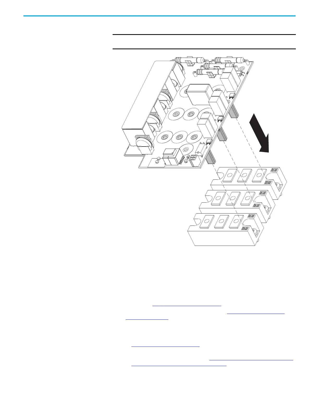
IMPORTANT Take care to connect the gate lead connectors on the back of the AC
precharge circuit board to the connectors on the IGBTs carefully.

 Loading...


