EasyManuals Logo
Home>Rockwell Automation>DC Drives>Allen-Bradley PowerFlex 755TS Series

Rockwell Automation Allen-Bradley PowerFlex 755TS Series User Manual

Rockwell Automation Allen-Bradley PowerFlex 755TS Series
196 pages
To Next Page IconTo Next Page
To Previous Page IconTo Previous Page
Page #169 background imageLoading...
Page #169 background image
Rockwell Automation Publication 750-TG101A-EN-P - June 2022 169
Chapter 6 Frame 7 Renewal Kits Installation
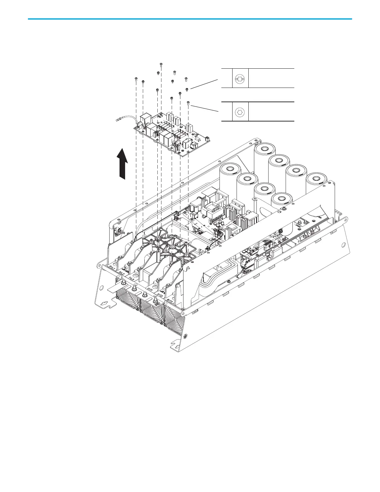
18. Remove the nine M4 x 8 mm slotted-Torx screws that secure the board to
the standoffs.
19. Remove the five M4 x 12 mm Torx screws that secure the board to the
plastic support tray, and remove the board.
Install the AC Precharge Circuit Board (400/480V)
Install the AC precharge circuit board in the reverse order of removal.
18
M4 x 8 mm
T20
2.6 N
m (23.0 lbin)
19
M4 x 12 mm
T20
2.6 N
m (23.0 lbin)

Table of Contents

Questions and Answers:

Question and Answer IconNeed help?

Do you have a question about the Rockwell Automation Allen-Bradley PowerFlex 755TS Series and is the answer not in the manual?

Rockwell Automation Allen-Bradley PowerFlex 755TS Series Specifications

General IconGeneral
BrandRockwell Automation
ModelAllen-Bradley PowerFlex 755TS Series
CategoryDC Drives
LanguageEnglish

Related product manuals