Rockwell Automation Publication 750-TG101A-EN-P - June 2022 35
Chapter 4 Frames 1…5 Renewal Kits Installation
Remove the Power Terminal
Cover, Frames 1…5
Remove the power terminal cover to access the power terminals, control pod
components, and internal stirring fans (where applicable). The terminal cover
is installed on Frame 1…5 drives with IP20, NEMA/UL Open Type, IP20, NEMA/
UL Type 1, and Flange, NEMA/UL Type 4X/12 back enclosures.
Remove the Power Terminal Cover, Frames 1…5
Follow these steps to remove the power terminal cover.
1. Review the Product Advisories
on page 11.
2. Turn off and lock-out incoming power. See Remove Power from the
System on page 12.
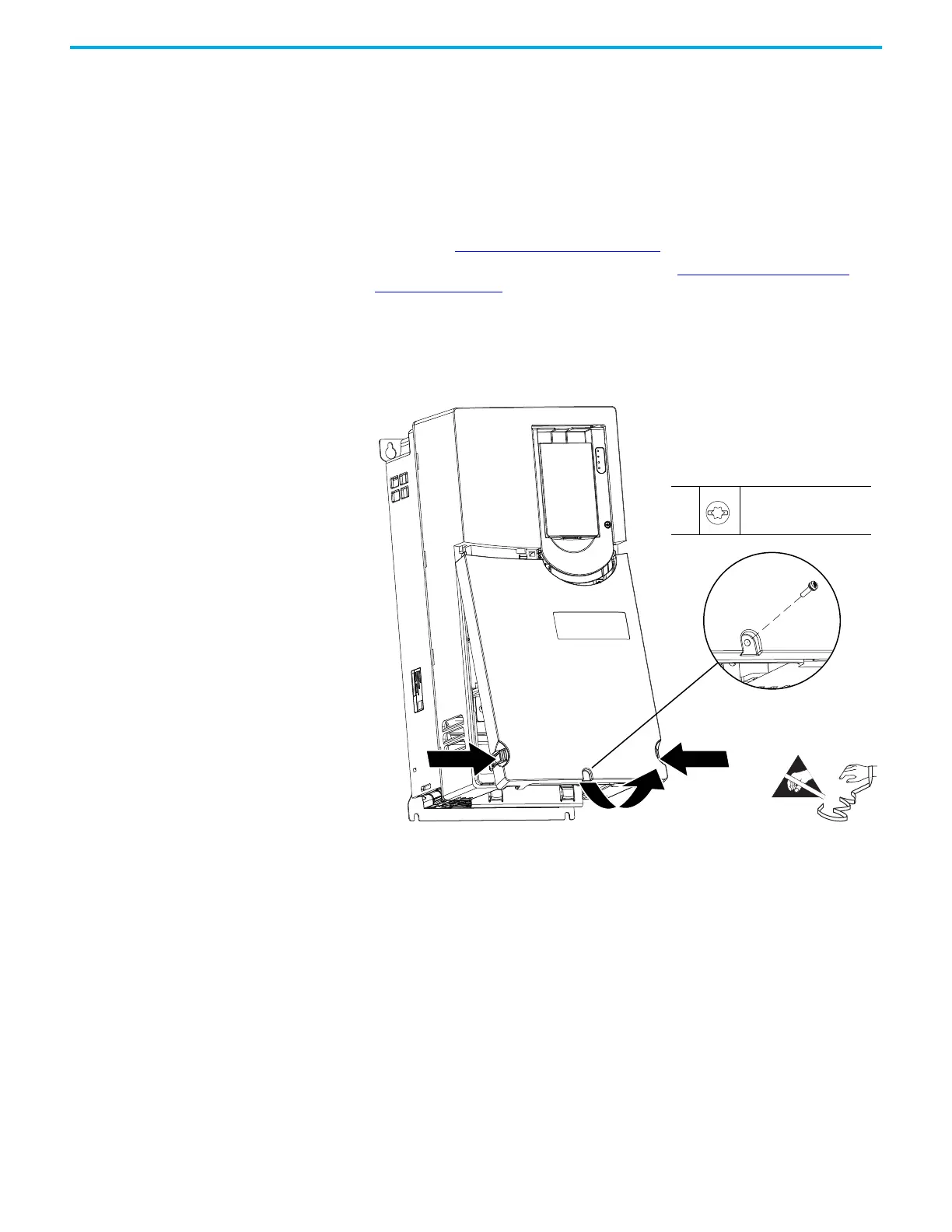
3. For IP20, NEMA/UL Type 1 enclosures only, remove the M4 x 16 mm
slotted-Torx screw that secures the cover to the conduit box. Retain the
screw for reuse.
4. Press inward on the two tabs on the lower left and right sides of the
terminal cover and rotate the cover out from the bottom of the chassis.
Frame 4 - Open Type Shown
NEMA / UL Type 1 Only
3
4
3
M4 x 16 mm
T20 or F - 6.4 mm (0.25 in.)
0.23 N•m (2.0 lb•in)

 Loading...


