76 Rockwell Automation Publication 750-TG101A-EN-P - June 2022
Chapter 4 Frames 1…5 Renewal Kits Installation
Install the Main Control Board to Power Interface Board Ribbon Cable,
Frames 2…5
Install the main control circuit board ribbon cable in the reverse order of
removal.
Backplane Circuit Board
Replacement, Frame 1
Replacement kit catalog number: SK-RT-BKPLN, SK-RT-BKPLN-XT
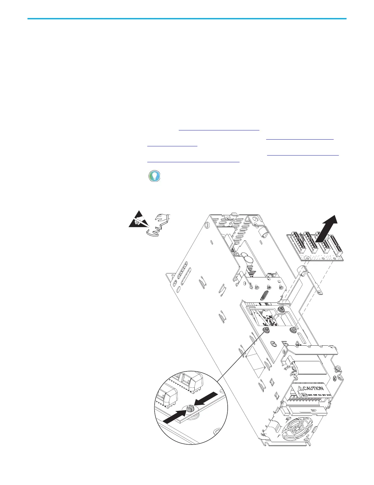
Remove the Backplane Circuit Board, Frame 1
Follow these steps to remove the backplane circuit board.
1. Review the Product Advisories
on page 11.
2. Turn off and lock-out incoming power. See Remove Power from the
System on page 12.
3. Remove the main control circuit board. See Remove the Main Control
Circuit Board, Frame 1 on page 64.
4. Compress the mounting two posts that secure the backplane circuit
board to the control pod chassis, push the posts through the mounting
holes on the board, and remove the board.
Retain the main control circuit board for reuse.
4 (Qty. 2)
Chassis Not Shown for Clarity Only

 Loading...


