54 Rockwell Automation Publication 750-TG101A-EN-P - June 2022
Chapter 4 Frames 1…5 Renewal Kits Installation
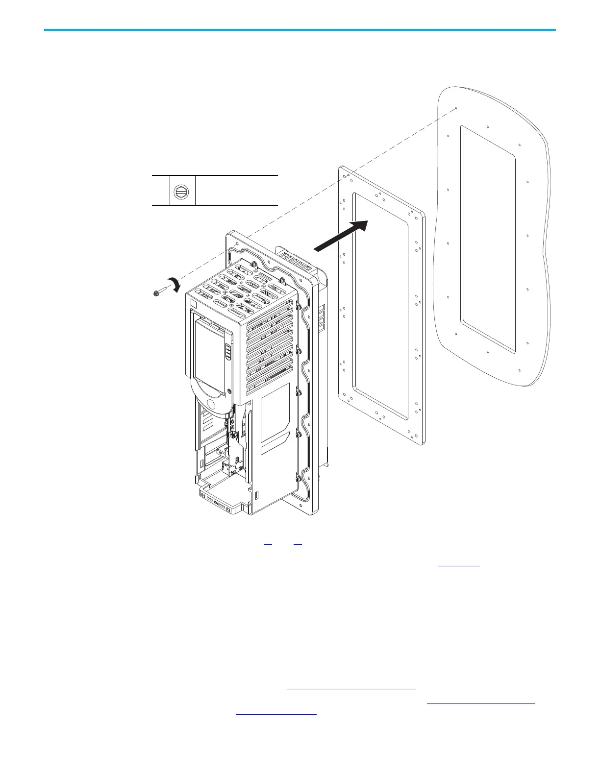
4. Place the gasket on the flange, insert the drive into the mounting surface,
and secure the flange and drive to the mounting surface the #10-16 x 1 in.
slotted-hex screws.
5. Replace any power wiring, I/O wiring, and communication cables. See
pages 13
and 14 for power terminal locations. For power terminal torque
specifications, see the PowerFlex 755TS Products with TotalFORCE
Control Installation Instructions, publication 750-IN119
.
Control Pod Printed Circuit
Board Fan Replacement,
Frames 2…5
Replacement kit catalog numbers: SK-RT-PODFAN1, SK-RT-PODFAN1-XT.
These kits can be used on all enclosure types.
Remove the Control Pod Printed Circuit Board Fan, Frames 2…5
Follow theses steps to remove the control pod printed circuit board fan.
1. Review the Product Advisories
on page 11.
2. Turn off and lock-out incoming power. See Remove Power from the
System on page 12.
4
#10-16 x 1 in.
5/16 in.
3.2 N•m (28.0 lb•in)

 Loading...


