140 Rockwell Automation Publication 750-TG101A-EN-P - June 2022
Chapter 6 Frame 7 Renewal Kits Installation
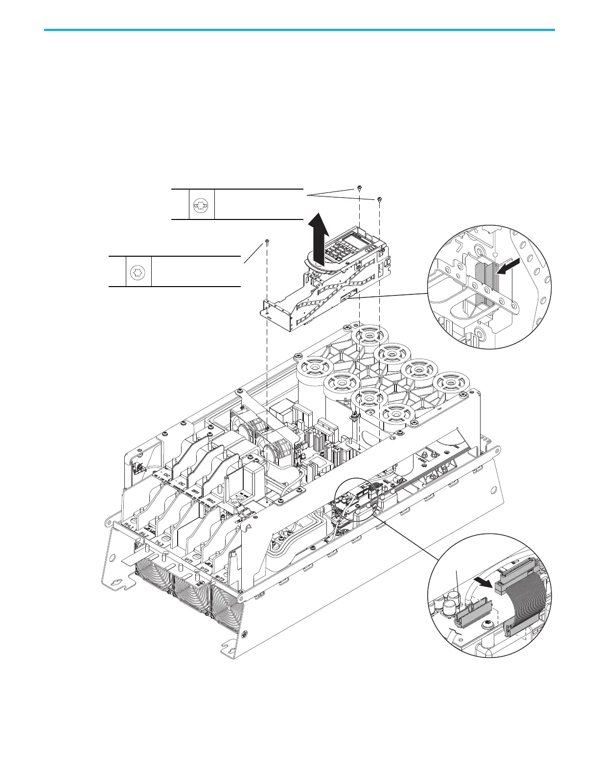
5. Remove the ribbon cable connector from the mounting tab on the inside
of the control pod chassis and push the cable through the bottom of the
chassis.
6. Remove the two M4 x 8 mm slotted-Torx screws that secure the upper
control pod chassis to the drive chassis.
7. Remove the M6 x 12 mm Torx screw that secures the lower control pod
chassis to the drive chassis.
8. Remove the control pod carefully from the drive and remove the ribbon
cable from the opening in the back of the control pod chassis.
9. Disconnect the ribbon cable from the power interface circuit board below
the control pod.
Install the Main Control Board to Power Interface Board Ribbon Cable
Install the main control board to power interface board ribbon cable in the
reverse order of removal.
6
M4 x 8 mm
T20
2.3 N
•m (20.0 lb•in)
7
M6 x 12 mm
T30
2.6 N
•m (23.0 lb•in)
5
9
8
J1

 Loading...


