64 Rockwell Automation Publication 750-TG101A-EN-P - June 2022
Chapter 4 Frames 1…5 Renewal Kits Installation
Main Control Circuit Board
Replacement, Frame 1
Replacement kit catalog number: SK-RT-MCB1-PF755, SK-RT-MCB1-PF755-XT
Remove the Main Control Circuit Board, Frame 1
Follow these steps to remove the main control circuit board.
1. Review the Product Advisories
on page 11.
2. Turn off and lock-out incoming power. See Remove Power from the
System on page 12.
3. Remove the power terminal cover. See Remove the Power Terminal
Cover, Frames 1…5 on page 35.
4. If used, disconnect the DPI cable from the connector on the bottom of
the HIM cradle.
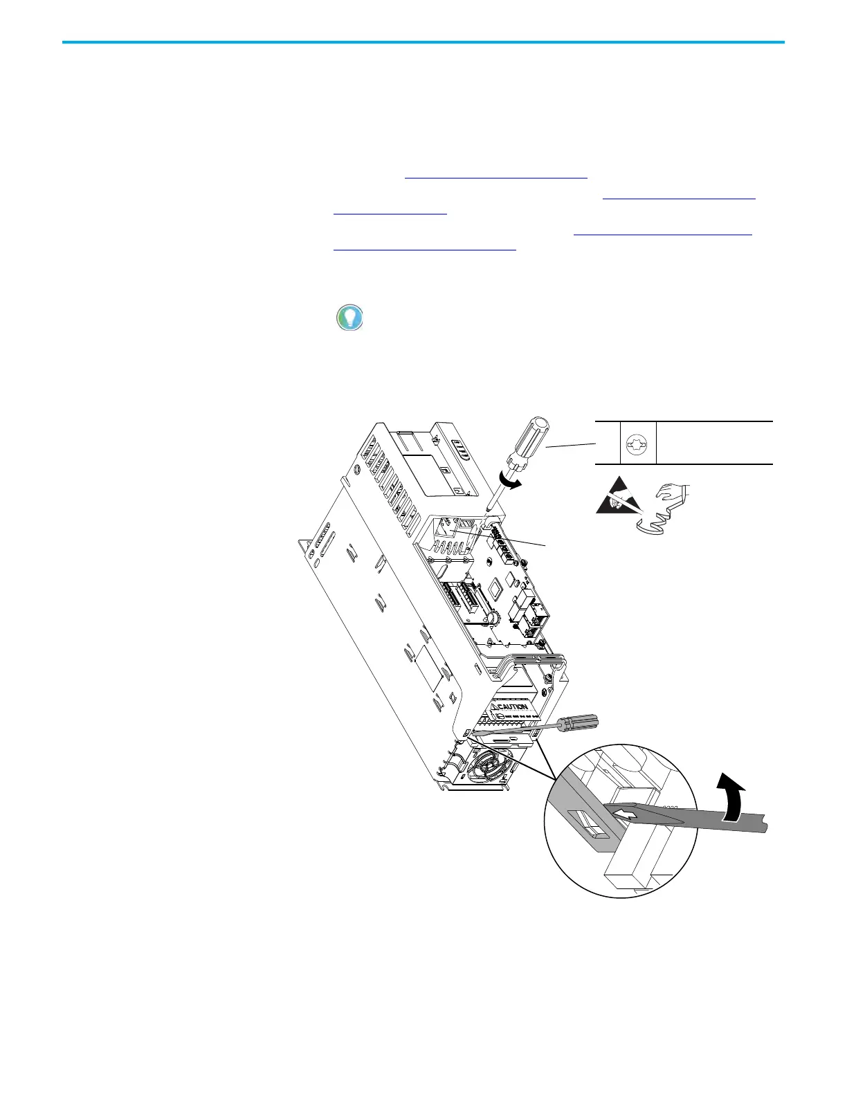
5. Loosen the captive M3 Torx screw that secures the plastic chassis to the
metal bracket.
6. Use a screwdriver to lift the two slotted-tabs on the bottom of the chassis
off the brackets.
If a cable is not connected to the DPI port on the HIM cradle, be sure to leave the
protective cover installed.
4
5
M4 x 16 mm
T20 or F - 6.4 mm (0.25 in.)
0.23 N•m (2.0 lb•in)
IP20, NEMA/UL Open Type
Frame 1 Drive Shown
6

 Loading...


