EasyManuals Logo
Home>Rockwell Automation>DC Drives>Allen-Bradley PowerFlex 755TS Series

Rockwell Automation Allen-Bradley PowerFlex 755TS Series User Manual

Rockwell Automation Allen-Bradley PowerFlex 755TS Series
196 pages
To Next Page IconTo Next Page
To Previous Page IconTo Previous Page
Page #137 background imageLoading...
Page #137 background image
Rockwell Automation Publication 750-TG101A-EN-P - June 2022 137
Chapter 6 Frame 7 Renewal Kits Installation
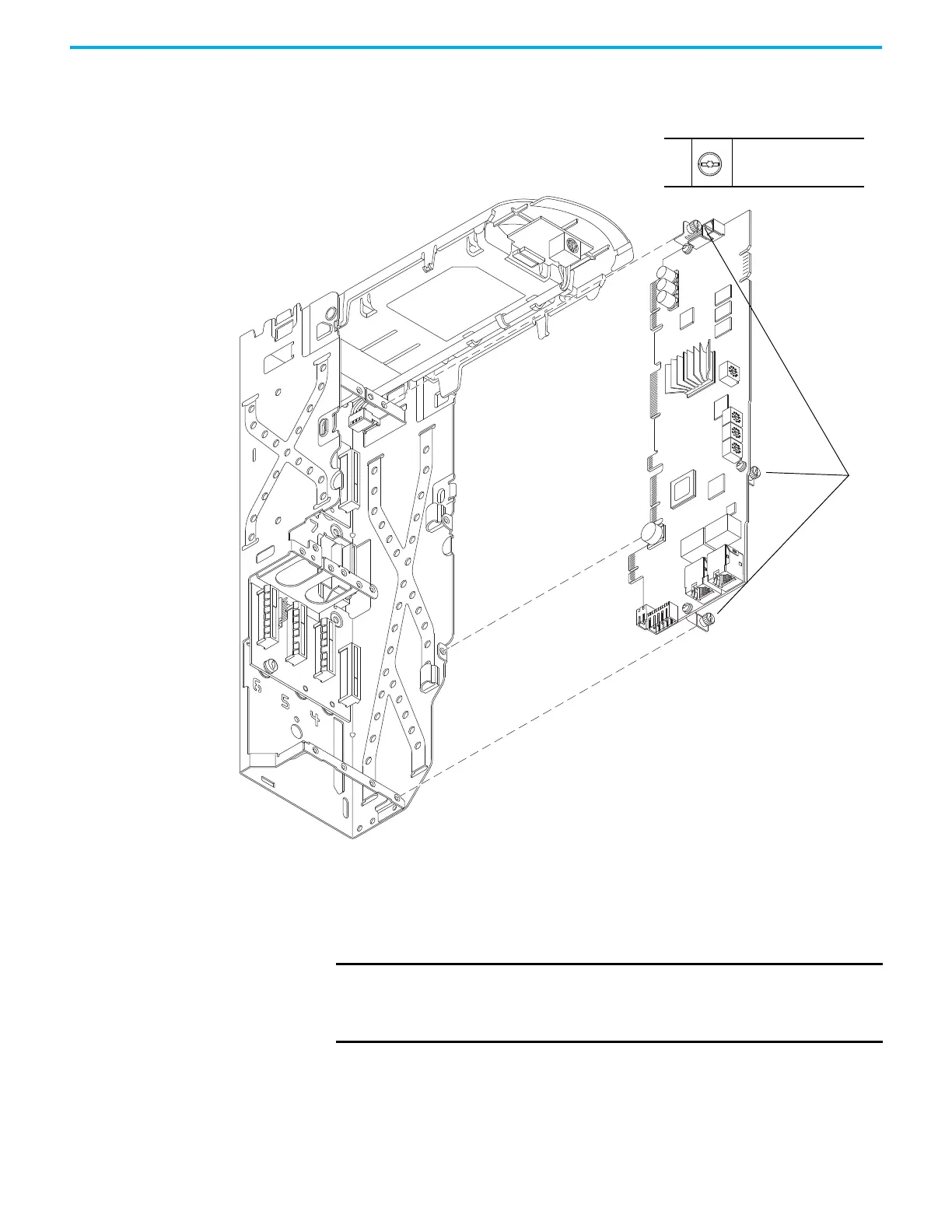
12. Loosen the three M3 captive slotted-Torx screws that secure the main
control circuit board to the control pod chassis and remove the main
control board.
Install the Main Control Circuit Board
Follow these steps to install the main control circuit board.
12
M3 x 6.4 mm
T15 or F - 5 mm (0.19 in.)
0.45 N•m (4.0 lb•in)
12
Control Pod Shown Separated from the Drive for Clarity Only.
IMPORTANT Circuit boards that are contained in renewal kits with XT contain dielectric
grease on the edge connectors, where present. Do not touch or remove the
grease from circuit board edge connectors. A non-greased connector can
lead to corrosion.

Table of Contents

Questions and Answers:

Question and Answer IconNeed help?

Do you have a question about the Rockwell Automation Allen-Bradley PowerFlex 755TS Series and is the answer not in the manual?

Rockwell Automation Allen-Bradley PowerFlex 755TS Series Specifications

General IconGeneral
BrandRockwell Automation
ModelAllen-Bradley PowerFlex 755TS Series
CategoryDC Drives
LanguageEnglish

Related product manuals