Rockwell Automation Publication 750-TG101A-EN-P - June 2022 141
Chapter 6 Frame 7 Renewal Kits Installation
Backplane Circuit Board
Replacement
Replacement kit catalog number: SK-RT-BKPLN, SK-RT-BKPLN-XT
This kit contains one circuit board. The frame 7 control pod contains two
backplane circuit boards. It is recommended that you replace both backplane
circuit boards simultaneously.
Remove the Backplane Circuit Board
Follow these steps to remove the backplane circuit board.
1. Review the Product Advisories
on page 11.
2. Turn off and lock-out incoming power. See Remove Power from the
System on page 12.
3. Remove the main control circuit board. See Remove the Main Control
Circuit Board on page 134.
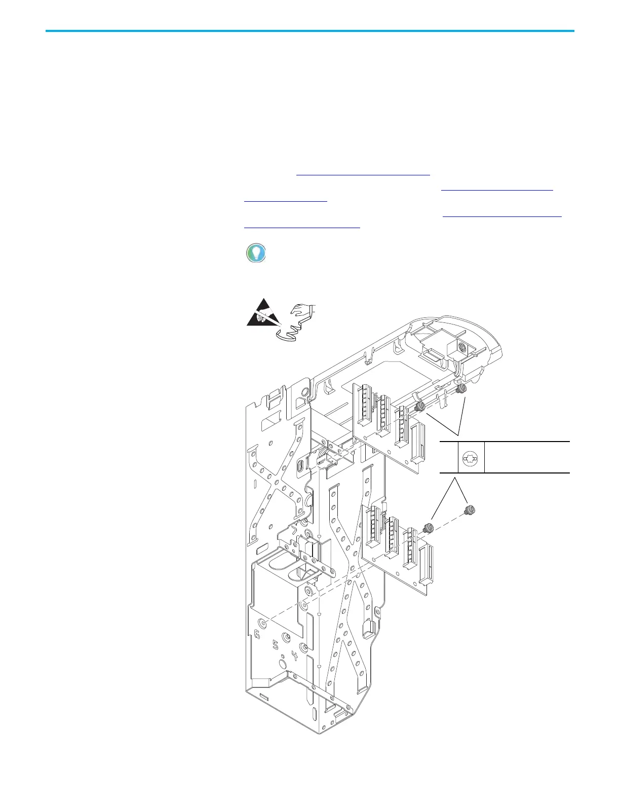
4. Remove the two M4 x 8 mm Torx screws that secure the backplane circuit
board to the pod chassis and remove the board.
Retain the main control circuit board for reuse.
4
M4 x 8 mm
T20 or F - 5 mm (0.19 in.)
2.6 N•m (23.0 lb•in)
Control Pod Shown Removed from the Drive Chassis for Clarity Only.

 Loading...


