40 Rockwell Automation Publication 750-TG101A-EN-P - June 2022
Chapter 4 Frames 1…5 Renewal Kits Installation
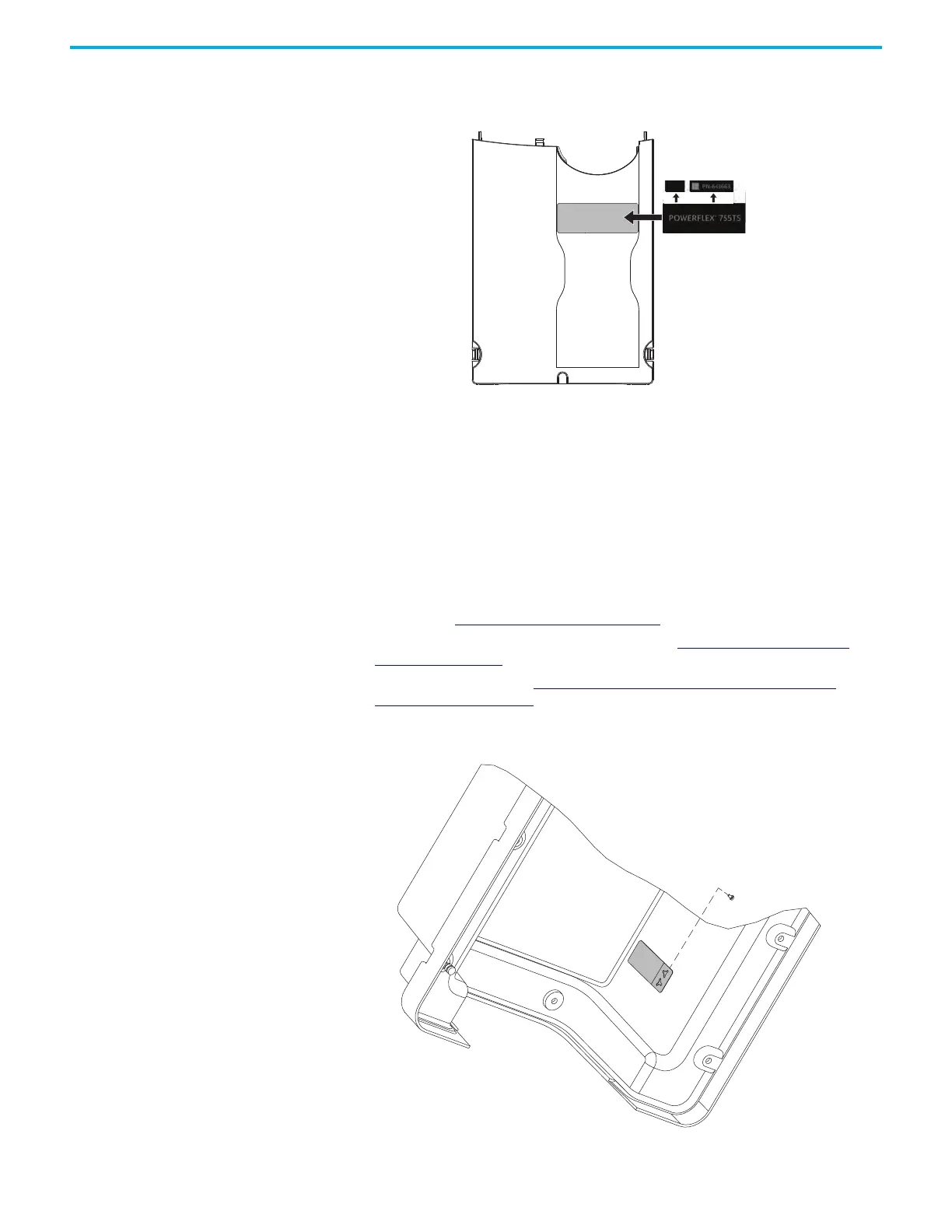
2. For all covers, apply the product label to the indentation on the cover.
3. Install the power terminal cover in the reverse order of removal.
IP54, NEMA/UL Type 12
Cover Replacement, Frames
2…5
Replacement kit catalog numbers: SK-RT-CVR12-F2, SK-RT-CVR12-F2-XT,
SK-RT-CVR12-F3, SK-RT-CVR12-F3-XT, SK-RT-CVR12-F4,
SK-RT-CVR12-F4-XT, SK-RT-CVR12-F5, SK-RT-CVR12-F5-XT
Remove the IP54, NEMA/UL Type 12 Cover, Frames 2…5
Follow theses steps to remove the cover.
1. Review the Product Advisories
on page 11.
2. Turn off and lock-out incoming power. See Remove Power from the
System on page 12.
3. Remove the cover. See Remove the IP54, NEMA/UL Type 12 Cover,
Frames 2…5 on page 37.
4. If present, remove any stored PE jumper retainer screws from the PE
retainer on the inside of the cover.
Frame 4 - Type 1 Cover Shown

 Loading...


