Rockwell Automation Publication 750-TG101A-EN-P - June 2022 49
Chapter 4 Frames 1…5 Renewal Kits Installation
Install the Chassis, Frames 2…5
Install the chassis in the reverse order of removal.
Flange Gasket Replacement,
Frames 2…5
Replacement kit catalog numbers: SK-RT-FG1-F2, SK-RT-FG1-F3,
SK-RT-FG1-F4, SK-RT-FG1-F5
This kit are used for flange, NEMA/UL Type 4X/12 back enclosures only.
Remove the Flange Gasket, Frames 2…5
Follow these steps to remove the flange gasket.
1. Review the Product Advisories
on page 11.
2. Turn off and lock-out incoming power. See Remove Power from the
System on page 12.
3. Remove the terminal cover from the drive. See Remove the Power
Terminal Cover, Frames 1…5 on page 35.
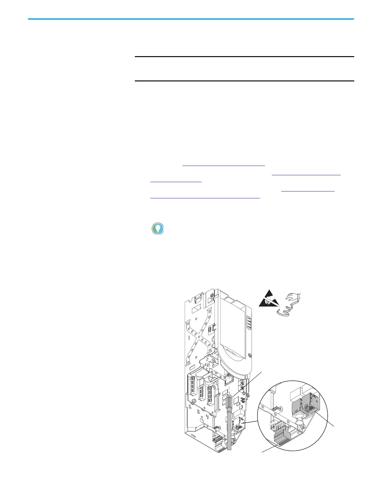
4. If used, disconnect the HIM DPI cable from the connector (port 2) on the
HIM cradle.
5. Disconnect any cables from the Ethernet connectors on the bottom of the
main control board in the control pod.
6. If used, disconnect the plug-in terminal block (TB1) on the bottom of the
main control board.
7. If an option module is installed, disconnect any I/O wiring terminal
blocks (not shown in image).
IMPORTANT For frames 4 and 5 drive, route the stirring fan power wire harness and
connector through the back side of the chassis before securing the chassis
to the drive frame.
If a cable is not connected to the DPI port on the HIM cradle, be sure to leave the
protective cover installed.
Control Pod Shown Separated
from the Drive for Clarity Only.
5
4
6

 Loading...


