Rockwell Automation Publication 750-TG101A-EN-P - June 2022 75
Chapter 4 Frames 1…5 Renewal Kits Installation
Main Control Board to Power
Interface Board Ribbon
Cable Replacement, Frames
2…5
Replacement kit catalog number: SK-RT-PIC1-F27-XT
Remove the Main Control Board to Power Interface Board Ribbon Cable,
Frames 2…5
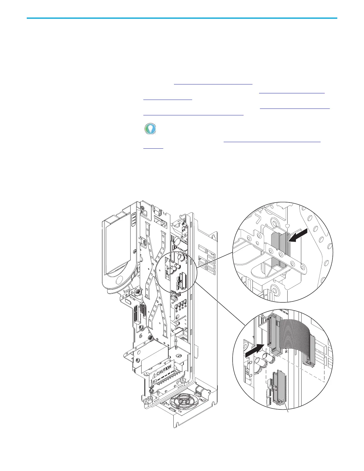
Follow these steps to remove the main control board to power interface board
ribbon cable.
1. Review the Product Advisories
on page 11.
2. Turn off and lock-out incoming power. See Remove Power from the
System on page 12.
3. Remove the main control circuit board. See Remove the Main Control
Circuit Board, Frames 2…5 on page 69.
4. Remove the drive chassis. See Remove the Chassis, Frames 2…5
on
page 46.
5. Remove the ribbon cable connector from the mounting tab on the inside
of the control pod chassis.
6. Pull the cable through the slot in the side of the control pod chassis.
7. Disconnect the ribbon cable connector from connector J1 on the power
circuit board, and remove the ribbon cable from the drive.
Retain the main control circuit board for reuse.

 Loading...


