Mounting
3.2 Mounting the motor
SINAMICS V90, SIMOTICS S-1FL6
100 Operating Instructions, 04/2019, A5E36037884-007
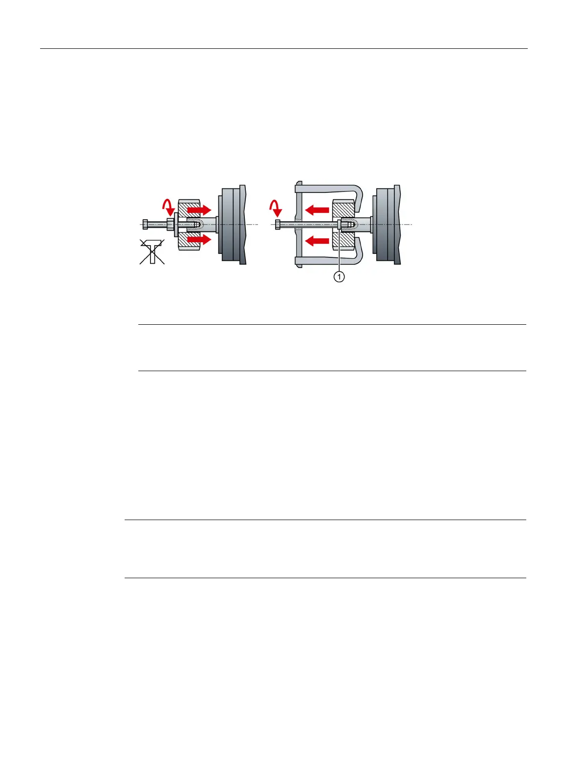
Mount or remove the power output elements (e.g. couplings, gear wheels, belt pulleys) using
suitable devices only (see figure).
● Use the threaded hole in the shaft extension.
● If required, heat up the output elements before mounting or removing.
● When removing the output elements, use an intermediate disk to protect the centering in
the shaft extension.
● If necessary, completely balance the motor together with the output elements according
to ISO 1940.
Note
Motors with feather key are half
-key balanced. The motors have been balanced with half
For motor dimension, see Section "Mounting orientation and dimensions (Page 89)".
The rated motor specifications are continuous allowable values at a surrounding air
temperature of 40 °C when the motor is installed with a steel flange. When the motor is
mounted on a small surface, the motor temperature may rise considerably because of the
limited heat radiating abilities of the surface. Make sure that you use a suitable flange
according to Siemens-recommended flange sizes.
Note
The actual temperature rise depends on how the flange (motor mounting section) is fixe
d on
the installation surface, what material is used for the motor mounting section, and motor
speed. Always check the actual motor temperature.

 Loading...


